AR14.10-P-3930BD | Remove/install left exhaust manifold | 15.2.12 |
ENGINE 112.945 in MODELS 463.209 /232 /233 /244 /245 /250
ENGINE 113.962 in MODELS 463.206 /240 /241 /247 /248 /249 /254
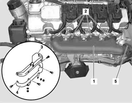
P14.10-2039-11
Shown on engine 113.982
1 Left exhaust manifold
2 Exhaust manifold nuts
3 Bolts
4 Seal
5 Heat shield (upper section)
6 Heat shield (lower section)
7 Ignition coils
9 Bolts on transverse exhaust pipe bracket
10 Downpipe
G 3/3 Left O2 sensor upstream of TWC
G3/3x1 Connector of left O2 sensor upstream of TWC
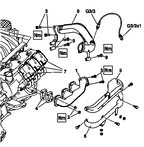
P14.10-0255-12
Shown on engine 112
1 Left exhaust manifold
2 Exhaust manifold nuts
3 Bolts
4 Seal
5 Heat shield (upper section)
6 Heat shield (lower section)
7 Ignition coils
8 Exhaust crosspipe
9 Bolts on transverse exhaust pipe bracket
G3/3 Left O2 sensor upstream of TWC
G3/3x1 Connector of left O2 sensor upstream of TWC
| Remove/install | ||
Danger! | Risk of explosion caused by escaping oxyhydrogen gas. Risk of injury caused by caustic burns to eyes, skin and mucous membranes from battery electrolyte (contains diluted sulfuric acid) or metal spatter due to short circuit. Risk of burn injuries caused by short circuit. Risk of poisoning caused by swallowing battery electrolyte (contains diluted sulfuric acid) or absorption of lead over the skin or orifices | No fire, sparks, open flames or smoking. Wear acid-resistant gloves and clothing and safety glasses with side guards. Do not place any conductive objects on the battery and avoid any short circuit from battery positive to ground. Only fill liquid battery electrolyte (diluted sulfuric acid) into suitable and appropriately marked containers. | |
1.1 | Disconnect ground line at battery | Installation: Code radio, clock and adjust stationary heater timer if necessary. | |
All models except Code 979. | |||
Model 463.241 with code 979 | |||
Model 463.248 with code 979 | |||
| Notes on battery | All models. | |
2 | Remove engine cover with integral air filter. | Remove by pulling vertically up and off the cylinder head covers. | |
3 | Remove ignition coils (7) on left side. | ||
4.1 | Remove left sensor (G3/3) with its connector (G3/3x1). | M112 only Makes it easier to remove the flange connection from the transverse exhaust pipe and left manifold. | |
5 | Remove the heat shield upper section (5). | The heat shield consists off two sections bolted together. | |
6 | Detach throttle cable from position sensor. | M113. only | |
7.1 | Separate the flange connection from transverse exhaust pipe (8) and left exhaust manifold (1). | Only model 463.206/ 209/ 232/ 233/ 240/ 241. | |
Installation: | |||
Replace rivet nuts in exhaust manifold. | |||
| |||
7.2 | Disconnect flange connection from down pipe (10) and left exhaust manifold (1) en | Only models 463.243/ 244/ 245/ 246/ 247/ 248/ 249/ 250/ 254. | |
Installation: | |||
Replace rivet nuts in exhaust manifold. | |||
| |||
8 | Separate connecting flange from cross-pipe (8) and left-side exhaust system. | Only model 463.206/ 209/ 232/ 233/ 240/ 241. | |
Installation: | |||
Replace rivet nuts in exhaust manifold. | |||
| |||
9 | Unscrew retaining bolts (9) of transverse exhaust pipe (8) from the transmission | | |
10 | Remove the heat shield lower section (6). | ||
11 | Remove left exhaust manifold (1) | Unscrew nuts (2) and extract exhaust manifold by lifting it upward. | |
Installation: Replace nuts (2), gaskets (4), studs. | |||
12 | Install in the reverse order | ||
13 | Read out fault memory with Hand-Held Tester (HHT) | ||
Read out fault memory and erase using STAR DIAGNOSIS | STAR DIAGNOSIS | ||
| Connect STAR DIAGNOSIS and read out fault memory | ||
Exhaust system
Number | Designation | Engines | |
BA49.10-P-1003-01A | Bolt of flange connection to crosspipe / exhaust system | Nm | 25 |
BA49.10-P-1004-01A | Bolt of exhaust cross pipe to transmission | Nm | 38 |
Exhaust manifold
Number | Designation | Engine | Engine 113.940/941/ | |
BA14.10-P-1001-01B | Nut to exhaust manifold | Nm | 16 | 16 |
Commercially available tools
Powiązane dokumenty
- ad0000p200004a Podłączanie STAR DIAGNOSIS, odczytywanie pamięci usterek
- ad0000p200004a
- ah5410p000101a
- ah5410p000101a Wskazówki dotyczące akumulatora
- ar1400p5303ag
- ar1512p2003a
- ar1512p2003a Demontaż i montaż cewek zapłonowych
- ar4910p553101da Wymiana nakrętek nitowanych przy kolektorze wydechowym
- ar5410p0003g Odłączanie, podłączanie przewodu masowego akumulatora
- ar5410p0003pm Odłączanie, podłączanie przewodu masowego akumulatora
- ar5410p0003pv
- ar5410p0003pv Odłączanie i przyłączanie przewodu masowego akumulatora
- as5410z000101a Niebezpieczeństwo pożaru/wybuchu z powodu zwarcia i wydostającego się gazu piorunującego. Niebezpieczeństwo obrażeń z powodu poparzenia oczu, skóry i śluzówki przez elektrolit akumulatora/mgiełkę lub przez zwarcie i działanie