
D05.20-1148-09
1 | Belt pulley | 4 | Camshaft sprocket | 7 | Hold-down tool | ||
2 | Web | 5 | Screw | 8 | Camshaft bearing cap | ||
3 | Screw | 6 | Camshaft bearing cap | 9 | Camshaft |
| Remove | ||
1 | Remove engine and install on assembly stand | ||
| 000 588 00 31 00 Assembly stand | ||
| 000 588 08 31 00 Mounting fork adapter | ||
2 | Remove cylinder head cover | ||
3 | Set piston on 1st cylinder to ignition top dead center (TDC) | ||
To do this rotate engine at crankshaft in direction of engine rotation until marking for a 0° crank angle on the belt pulley (1) coincides with stay (2) on the crankcase. | |||
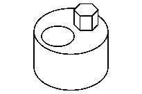
Counterholder | |||
Counterholder | |||
4 | Loosen screw/bolts (3) until the camshaft sprocket (4) can be turned on the camshafts (9) | Note the left-hand thread of the screw/bolts (3). | |
5 | Turn camshafts (9) until the markings (arrow A) are aligned with the tip (arrow B) of the camshafts (9) | | |
6 | Remove camshaft bearing cap (6) | To do this mark camshaft bearing cap (6), remove screw/bolts (5) and remove camshaft bearing cap (6). | |
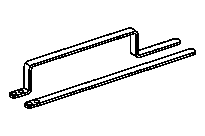
7 | Place hold-down tool (7) free of tension on camshafts (9) and install hand-tight. | Holddown device | |
| Check | ||
8 | Check whether the marking 0° crank angle on the belt pulley (1) coincides with the stay (2) on the crankcase; align belt pulley (1) if necessary | Counterholder | |
Counterholder | |||
| Remove | ||
9 | Tighten screw/bolts (3) until the camshaft sprocket (4) can no longer be turned on the camshafts (9) | Note the left-hand thread of the screw/bolts (3). | |
10 | Remove chain tensioner | ||
11 | Remove hold-down tool (7) | Holddown device | |
12 | Remove camshaft bearing cap (8) | ||
To do this remove screw/bolts for the camshaft bearing cap (8) step by step. | |||
13 | Remove camshafts (9) | To do this remove timing chain from the camshaft sprockets (4) and remove camshafts (9). Secure timing chain against falling into the timing case shaft. Cover over timing case slot with a clean rag. | |
Adjust | |||
14 | Clamp in camshafts (9) on the truncations for hold-down tool (7) in a vise | | |
15 | Mark camshaft sprocket (4) relative to the camshaft (9) | ||
16 | Tighten screw/bolts (3) | Pay attention to markings on the camshaft sprockets (4). Note the left-hand thread of the screw/bolts (3). | |
Screw/bolt, camshaft sprocket to camshaft | |||
If the camshaft sprockets (4) turn when tightening the screw/bolts (3): | |||
| |||
Loosen screw/bolts (3) again, align the camshaft sprocket (4) again and tighten screw/bolts (3). | |||
17 | Remove camshafts (9) from vise | ||
| Install | ||
18 | Insert camshaft sprocket (4) in timing chain and insert camshafts (9) in the bearing halves of the cylinder head | Lubricate bearing points. Insert camshafts (9) in such a way that the markings (arrow B) are aligned with the markings (arrow A) and the hold-down tool (7) can be installed free of tension. | |
19 | Install down hold-down tool (7) and install camshaft bearing cap (8) for the camshafts (9) | ||
Tighten down screw/bolts for the camshaft bearing cap (8) step by step. Check camshafts (9) for unobstructed movement; reinsert as required. Lubricate bearing points. | |||
Bolt, camshaft bearing cap to cylinder head | |||
Holddown device | |||
20 | Remove hold-down device (7) | Holddown device | |
21 | Insert camshaft bearing cap (6) and screw in screw/bolts (5) | Lubricate bearing points. | |
Bolt, camshaft bearing cap to cylinder head | |||
22 | Install chain tensioner | ||
| Check | ||
23 | Check basic position of camshafts (9) | ||
| Install | ||
24 | Install cylinder head cover | ||
25 | Install engine |

651 589 09 40 00
Holddown device
651 589 00 40 00
Counterholder
651 589 08 40 00
Counterholder