
A | Marking on intake camshaft |
B | Marking on camshaft bearing cap |
C | Marking in bore for rpm sensor |
D | Edge cutout of the sensor rotor for the exhaust camshaft |
D05.10-1176-06
| Remove/install | ||
1 | Remove engine cover | ||
2 | Remove engine oil filler neck | ||
3 | Remove rpm sensor from the camshaft | ||
4 | Set piston on cylinder 1 to TDC (TDC) | ||
Counterholder | |||
Counterholder | |||
| Check | ||
5 | Check setting of the intake camshaft | The marking on the intake camshaft (A) must coincide with the marking on the camshaft bearing cap (B). If the marking on the intake camshaft (A is not visible, turn the crankshaft through another revolution and check again. | |
If the marking on the intake camshaft (A) does not coincide with the marking on the camshaft bearing cap (B): | |||
| |||
Set basic position of camshafts. | |||
Set basic position of camshafts | |||
6 | Check setting of exhaust camshaft | Use a suitable mirror for checking. The edge cutout of the sensor rotor of the exhaust camshaft (D) must be aligned with the marking in the bore for the rpm sensor (C). | |
If the edge cutout of the sensor rotor of the exhaust camshaft (D) is not aligned with the marking in the bore for the rpm sensor (C): | |||
| |||
Set basic position of camshafts. | |||
Set basic position of camshafts | |||
7 | Install in the reverse order |
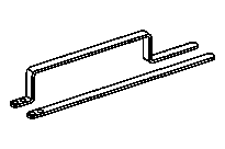
651 589 00 40 00
Counterholder
651 589 08 40 00
Counterholder