
Overview of camshafts |
01a | Holding device |
01b | Holding device |
02a | Bracket |
02b | Bracket |
03 | Bearing brackets |
04 | Bolts |
P05.10-2472-06

View from front |
1 | Segment disc |
1a | Edge |
2 | Segment disc |
2a | Bearing slot |
3 | Cylinder head cover |
P05.10-2471-06

05 | TDC marking |
06 | Positioning edge on the timing case cover |
4 | Telescope mirror |
D05.20-1158-06
Warning | Risk of injury. Skin or eye injuries may result when handling hot or glowing objects. | Wear protective gloves, protective clothing and safety glasses, if necessary. | |
Warning | Risk of injury. Moving parts can pinch, crush or, in extreme cases even sever extremities. | No parts of the body or limbs should be within the operating area of mechanical components when moving components. | |
Caution | Risk of injury caused by scraping or cutting body parts on sharp vehicle parts | Always wear protective gloves when working on or near sharp and non-deburred vehicle parts. | |
Caution | Risk of injury to skin and eyes due to handling of engine oil. Risk of poisoning caused by swallowing engine oil | Wear protective gloves, protective clothing and safety glasses. | |
Topical note | Notes on avoiding damage through contamination and foreign objects | ||
| Remove | ||
1 | Remove cylinder head cover (3). | ||
2 | Remove the chain tensioner. | ||
3 | Remove the camshaft positioner. | ||
Adjust | |||
4 | Rotate the engine at crankshaft center bolt in direction of engine rotation with the aid of a telescope mirror (4) to ignition TDC on cylinder 1. | The TDC marking (05) on the belt pulley must align with the positioning edge on the timing case cover (06). | |
WIS Service Media | |||
Commercially available devices/tools | |||
Socket wrench bit | |||
5 | Turn camshafts in the basic position. | | |
The camshafts are in the basic position if, on the exhaust camshaft, the edge (1a) of the partial segment of the segment disc (1) and the bearing slot (2a) on the segment disc (2) point vertically upwards. | |||
Socket | |||
6 | Install holding devices (01a, 01b). | Holding device | |
7 | Screw in screws (04). | The bearing brackets (03) must lie flat on the cylinder head. | |
8 | Install brackets (02a, 02b). | | |
| |||
Socket | |||
Holding device | |||
| Install | ||
9 | Install camshaft positioners. | ||
Screw in control valves and allows to touch. Tightening of the control valves first take place after installation of the chain tensioner. During mounting of the camshaft positioner or the timing chain ensure that the crankshaft does not turn. | |||
10 | Install the chain tensioner. | ||
11 | Tighten control valves of the camshaft positioners. | ||
12 | Remove brackets (02a, 02b) from holding device (01a). | The holding devices (01a, 01b) remain mounted on the cylinder head. | |
Holding device | |||
13 | Loosen screws/bolts (04) at holding devices (01a, 01b) until the camshafts can be rotated. | The holding devices (01a, 01b) remain mounted on the cylinder head. | |
Holding device | |||
| Check | ||
14 | Rotate the engine at crankshaft center bolt in direction of engine rotation with the aid of a telescope mirror (4) to ignition TDC on cylinder 1. | The TDC marking (05) on the belt pulley must align with the positioning edge on the timing case cover (06). | |
WIS Service Media | |||
Commercially available devices/tools | |||
Socket wrench bit | |||
15 | Hand tighten screws/bolts (04) at holding devices (01a, 01b). | Screw screw/bolts (04) until the bearing brackets (03) lie flat on cylinder head. | |
Holding device | |||
16 | Install brackets (02a, 02b) on holding device (01a). | | |
The basic position of the camshaft is checked through installation of the bracket (02a, 02b). | |||
Holding device | |||
If the brackets (02a, 02b) cannot be installed, | |||
| |||
repeat adjustment of the basic position of the camshafts. | |||
17 | Remove the brackets (02a, 02b) and holding devices (01a, 01b). | Holding device | |
18 | Install cylinder head cover (3). | ||
| Check | ||
Warning | Risk of burn injuries, suffocation and poisoning when working on the exhaust system and the components connected to it. Risk of suffocation and risk of poisoning caused by inhalation of gaseous and solid components of the exhaust. Risk of poisoning caused by skin contact with solid components of the exhaust. | Wear protective clothing and safety glasses. Use the extraction system. Move people out of the hazard area. | |
Warning | Risk of accident from vehicle starting off by itself when engine running. Risk of injury (bruises and burns) resulting from working on the engine while it is being started or when it is running. | Secure vehicle to prevent it from starting off by itself. Wear closed and snug-fitting work clothes. Do not touch hot or rotating parts. | |
19 | Perform engine test run. While doing so, check engine for proper operation and leak tightness. |


270 589 01 61 00
Holding device
001 589 65 09 00
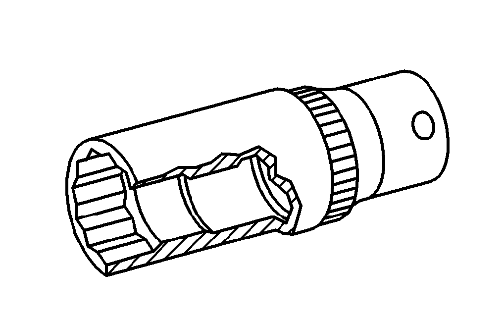
Socket wrench bit
270 589 01 07 00
Socket
Powiązane dokumenty
- ah0000p500001a Wskazówki dotyczące zapobiegania uszkodzeniom na skutek zabrudzeń i ciał obcych
- ar0120d5014tsc
- ar0510d7800tsc
- ar0520d7204tsc
- as0000z000201a Niebezpieczeństwo zranienia skóry i oczy na skutek kontaktu z gorącymi lub żarzącymi się przedmiotami
- as0000z000501a Niebezpieczeństwo wypadku na skutek samoczynnego ruszenia przy pracującym silniku. Niebezpieczeństwo obrażeń na skutek zmiażdżenia lub poparzenia przy wykonywaniu czynności podczas rozruchu lub przy pracującym silniku.
- as0000z000901a Niebezpieczeństwo zakleszczenia lub zmiażdżenia, w skrajnym przypadku obcięcia kończyn podczas prac przy układach mechanicznych.
- as0000z001701a Niebezpieczeństwo obrażeńo elementy pojazdu o ostrych krawędziach.
- as1800z000101a Niebezpieczeństwo obrażeń skóry i oczu podczas kontaktu z olejem silnikowym. Niebezpieczeństwo zatrucia wskutek połknięcia oleju silnikowego
- as4900z000101a Niebezpieczeństwo poparzenia, uduszenia i zatrucia podczas prac przy układzie wydechowym i połączonych z nim elementach. Niebezpieczeństwo uduszenia i zatrucia przez wdychanie gazowych i stałych składników spalin. Niebezpieczeństw