
452 589 01 63 00
Clip remover

1 | Release and disconnect electrical connector (1) from the low-temperature circuit coolant pump. |
2 | Detach clamp (2) of the electrical wiring harness. |
3 | Release and disconnect electrical connector (3) from the low-temperature circuit valve. |
4 | Release and disconnect electrical connector (4) from the coolant temperature sensor. |
5 | Model 447 with code HH4 (THERMOTRONIC automatic climate control), model 447 with code HH9 (TEMPMATIC semi-automatic controlled air conditioning) |
6 | Unclip outside temperature sensor (6). |
S01.10-A031-76

S01.10-A032-77
7 | Remove cable tie (7) from the engine and vehicle wiring harness. |
8 | Unclip retaining clip (8) with the clip remover and release and disconnect electrical connector (9) from the fan unit. |
9 | Remove bottom area of the heat insulation (10) from the frame. |
Do not remove heat insulation (10). |

S01.10-A033-77
Shown on heat insulation removed |
10 | Remove cap (11) of the fuse box. |
11 | Remove nuts (12) and remove electric lines (16.1). |
12 | Unclip electrical connector (13) and release and disconnect. |
13 | Detach clamps (14) from the bracket (15). |
14 | Remove electric lines (16.1, 16.2) from the frame and guide under the heat insulation. |
15 | Tie electric lines (16.1, 16.2) to the engine. |
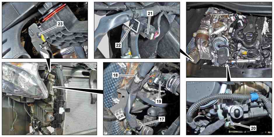
S01.10-A034-79
16 | Disconnect electrical connector (17) from the AdBlue® metering valve. |
17 | Detach clamp (18) of the electrical wiring harness. |
18 | Release and disconnect electrical connector (19) from the NOx sensor control unit upstream of the diesel oxidation catalytic converter. |
19 | Release and disconnect electrical connection (20) at separating point, and remove the electrical wiring harness from the engine. |
20 | Release and disconnect electrical connector (21) from the differential pressure sensor (22). |
21 | Remove screw (23) and tie differential pressure sensor (22) to the engine. |

S01.10-A035-77
Shown on model 447 except code ZG2 (permanent all-wheel drive) |
22 | Model 447 with code FY1 (Anti-Theft Protection Package) |
23.1 | Model 447 with code LG2 (LED Intelligent Light System) except code ZG2 (permanent all-wheel drive) |
23.2 | Model 447 with code LG2 (LED Intelligent Light System) with code ZG2 (permanent all-wheel drive) |

S01.10-A036-78
Shown on model 447 with transmission 711.6 |
24 | Raise vehicle. |
25 | Unclip retaining clip (29) with clip remover. |
The routing and attachment of the electrical wiring harness (33) may vary depending on equipment installed. |
26 | Release and disconnect electrical connectors (30) from the steering gear engine (31). |
27 | Detach clamp (32) and bring electrical wiring harness (33) out of the working area. |

S01.10-A037-78
Shown on model 447 with transmission 711.6 |
28 | Model 447 with transmission 711.6 |
29 | Model 447 with transmission 711.6 |
30 | Model 447 with transmission 711.6 |

S01.10-A038-78
Shown on model 447 with transmission 725.0 except code ZG2 (permanent all-wheel drive) |
31 | Model 447 with transmission 725.0 |
32 | Model 447 with transmission 725.0 |
33 | Model 447 with transmission 725.0 |
34 | Install in the reverse order. |
Powiązane dokumenty
- ah0000n000101a Wskazówki dotyczące samozabezpieczających śrub i nakrętek
- ah5400p000101a Wskazówki dotyczące zapobiegania uszkodzeniom elementów elektronicznych na skutek rozładowania potencjału elektrostatycznego