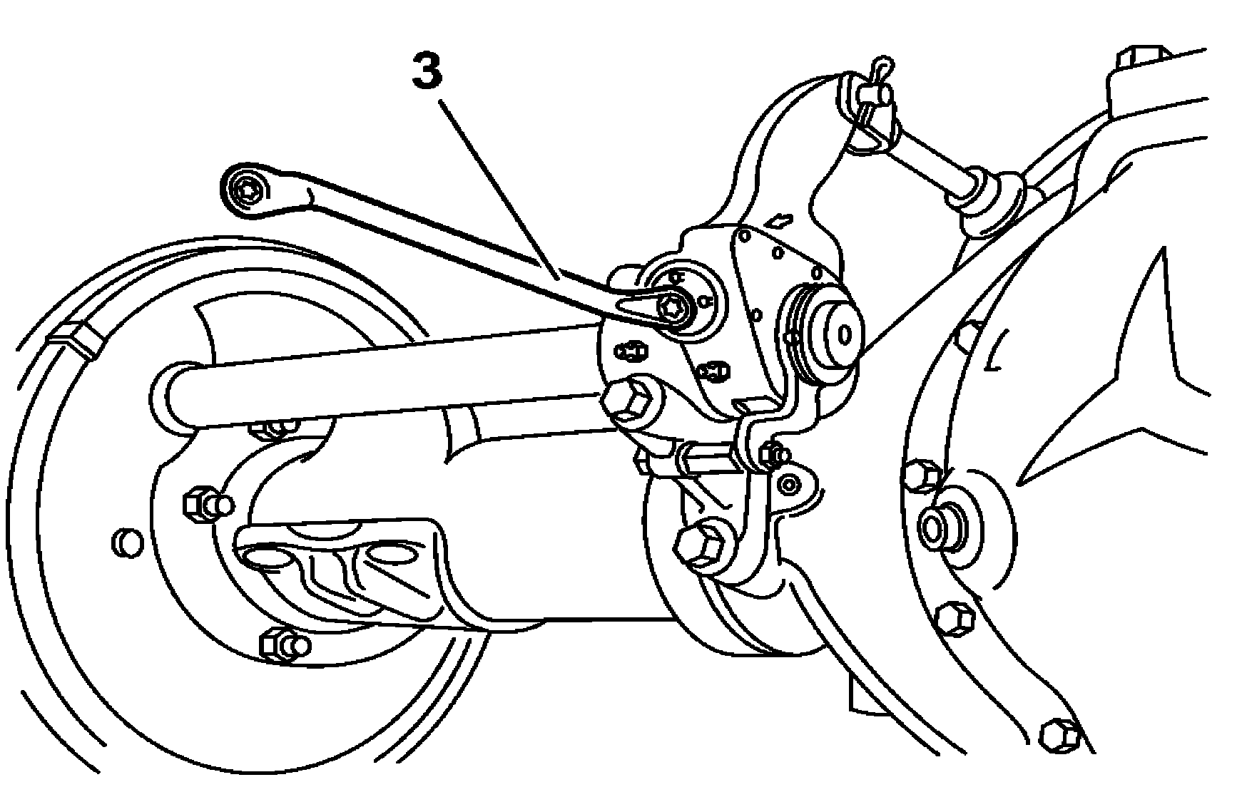
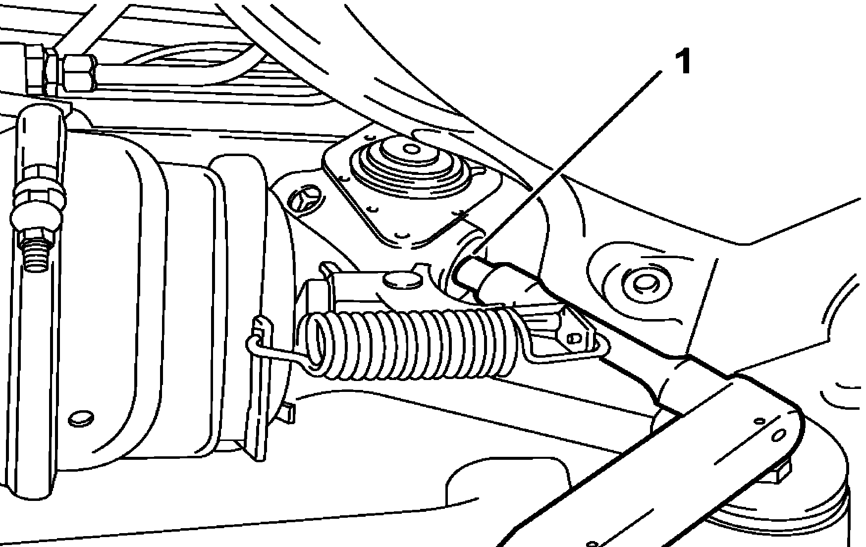
Mechanical adjustment screw | |
Control lever screw | |
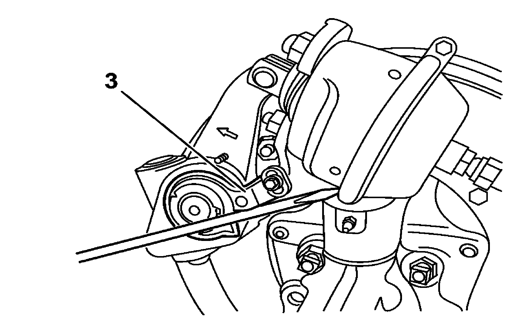
Control lever |
B42.00-0003-01
B42.00-0002-01

B42.00-0001-01
B42.00-0004-01
| Check | ||
Warning | Risk of accident from vehicle starting off by itself when engine running. Risk of injury (bruises and burns) resulting from working on the engine while it is being started or when it is running. | Secure vehicle to prevent it from starting off by itself. Wear closed and snug-fitting work clothes. Do not touch hot or rotating parts. | |
1 | Run the engine until the operating pressure is achieved in the pneumatic braking system | .Operating pressure | |
2 | Chock the wheels and release the parking brake | ||
Danger | Risk of death caused by vehicle slipping or toppling off of the lifting platform. | Align vehicle between vehicle lift columns and position the four support plates at the vehicle lift support points specified by the vehicle manufacturer. | |
3 | Lift the vehicle | ||
4 | Loosen the mechanical adjustment screw (1) clockwise until the pads touch the brake drum, then return it by one turn | ||
5 | Loosen by two turns the control lever screw (2) | ||
6 | Force the control lever (3) on the brake application direction (arrow direction) until it meets resistance, touching the internal stop of the governor | To avoid stress on the control lever if it becomes spaced apart from the bracket, the difference should be offset with washers placed between the lever and the bracket. | |
7 | Tighten the screw (2) of the control lever (3) | ||
8 | Actuate the brake pedal several times and check the operation of the governor | Each actuation of the pedal should correspond to a small clockwise displacement of the mechanical adjustment screw (1). Such displacement will cease as the prescribed clearance between the brake linings and drum is reached | |
Viewing the governor operation will be easier by leaving the wrench seated on the mechanical adjustment screw (1). | |||
.Clearance between the brakepad and brake drum | |||
9 | Actuate the brake pedal a few more times and check the free rotation of the wheels | Perform the control operation for all wheels. | |
10 | Run the engine until the operating pressure is achieved in the pneumatic braking system | .Operating pressure | |
11 | Chock the wheels and release the parking brake | ||
12 | Apply counterclockwise the prescribed torque to the mechanical adjustment screw (1) | If the tapered coupling slides at a torque below the indicated torque, remove the governor for repair. | |
.Bolt of the unidirectional conical coupling of the automatic adjuster |
참조 문서
- as0000z000501a 엔진이 작동 중인 상태에서 급발진에 의한 사고 위험 시동 또는 구동 중인 엔진 근처에서 작업할 때 차량에 부딪히거나 열에 의한 상해 위험
- as0000z001001a 리프터에서 차량이 미끄러지거나 틸팅 시 생명의 위험