
P05.10-2334-09
1 Exhaust camshaft
5 Center valve of exhaust camshaft
9 Pulse wheel of exhaust camshaft
17 Auxiliary bearing cap of exhaust camshaft
23 Tensioning rail bolts
24 Tensioning rail
13 Camshaft adjuster of exhaust camshaft
15 Camshaft adjuster for intake camshaft

P05.20-2234-04
13 Camshaft adjuster of exhaust camshaft
15 Camshaft adjuster for intake camshaft
18 Dowel pin
19 Pin
20 Bore in camshaft adjuster

P05.20-2235-10
21 Dowel pin in camshaft adjuster
22 Fitted bore on exhaust camshaft
Modification notes
| Remove/install | ||
1 | Remove air filter housing | ||
2 | Remove front covers from cylinder heads | Front cover on the right | |
Front cover on the left | |||
3 | Remove centrifuge | ||
4 | Crank engine at crankshaft center bolt in direction of engine rotation to a 40° crankshaft angle after ignition TDC and check position of camshafts | ||
| |||
5 | Lock gear backlash compensation for camshaft adjuster (13) at right exhaust camshaft (1) | ||
6 | Loosen center valve (5) on right exhaust camshaft (1) | ||
| |||
7 | Remove right cylinder head cover | ||
8 | Remove center valve (5) for right exhaust camshaft (1) and remove pulse wheel (9) | Check dowel pin (18) and pin (19). If dowel pin (18) or pin (19) has sheared off, it must be removed from camshaft adjuster (13). | |
Installation: Always replace pulse wheel (9). When tightening center valve (5), there is a risk that dowel pin (18) or pin (19) on pulse wheel (9) may shear off. Lubricate center valve (5) at contact surface to pulse wheel (9) before assembly. | |||
Installation: Align dowel pin (18) on pulse wheel (9) with bore (20) in the camshaft adjuster (13). | |||
9 | Counterhold right rear exhaust camshaft (1) using a suitable tool and detach camshaft adjuster (13) from right exhaust camshaft (1) in the forward direction | Installation: Align dowel pin (21) in camshaft adjuster (13) to fitted bore (22) in exhaust camshaft (1) and install camshaft adjuster (13) in its basic position: | |
See "Check basic position of camshafts". | |||
10 | Remove auxiliary bearing cap (17) on right exhaust camshaft (1) and take out exhaust camshaft (1) | | |
11 | Remove chain tensioner | Installation: Install new chain tensioner. The previously installed chain tensioner must not be reinstalled because during removal, its pressure pin is pressed into the end position. The thrust pin latch prevents this return stroke. This would overstretch the timing chain on reinstalling. | |
12 | Remove tensioning rail bolt (23) | Installation: Apply sealant to tensioning rail bolts (23) before assembly. | |
| |||
| |||
Loctite 5970 sealant | |||
13 | Pull tensioning rail (24) up and out of timing case | ||
14 | Install in the reverse order |
Camshaft, camshaft adjustment
Number | Designation | Engine | Engine | ||
BA05.20-P-1009-02A | Center valve for pulse wheel/camshaft adjuster to camshaft | Nm | 145 | 145 | |
BA05.20-P-1010-02A | Bolt, auxiliary bearing cap to cylinder head | Stage 1 | Nm | 8 | 8 |
Stage 2 | ° | - | - | ||
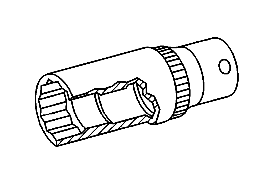


Wrench socket
001 589 65 09 00
116 589 20 33 00
116 589 01 34 00
Threaded stud
Impact extractor
Repair materials
Number | Designation | Order number |
BR00.45-Z-1013-01A | Loctite 5970 sealant | A 003 989 98 20 |
참조 문서
- ar0120p2100rx
- ar0120p5014ry
- ar0120p5014ry 실린더 헤드 후드 탈, 장착
- ar0130p5700rx
- ar0130p5700ry
- ar0130p580004v 실린더 헤드의 가이딩 블레이드 나사를 제거하십시오.
- ar0510p7800rx
- ar0520p601001vb 캠 샤프트의 기본위치를 점검하십시오.
- ar0520p720105va 톱니 백래시 보정의 제동
- ar0520p720106va 중앙 밸브 풀기, 고정
- ar0910p1150rx