AR05.20-D-6010SD | Check basic position of camshafts | 16.6.10 |
ENGINES 646.984 /985 /986 /989 /990 in MODEL 906

D13.22-1105-04
1 Center bolt
2 Belt pulley with vibration damper

D05.20-1120-06
3 Intake camshaft
4 Retaining pin
| Removing | ||
1 | Remove cylinder head cover | ||
2 | Position piston of cylinder 1 to ignition TDC | Crank engine at center bolt (1) and place belt pulley with vibration damper (2) on the marking (arrow A). The cams on the intake camshaft (3) and exhaust camshaft must lie obliquely upwards on cylinder 1; turn engine through one more revolution if necessary. | |
Socket wrench bit | |||
3 | Interlock intake camshaft (3) using retaining pin (4) (arrow B). | Retaining pins | |
| Checking | ||
4 | Check basic position | The markings on the camshaft sprockets must be positioned opposite each other (arrows C). The markings on the intake camshaft (3) and exhaust camshaft must be aligned with each other (arrows D). | |
If the markings (arrow C) are not opposite each other or aligned with the markings on the camshaft bearing covers (arrows D), the intake camshaft (3) and the exhaust camshaft must be removed and installed appropriately twisted. See: | |||
Remove/install camshafts | |||
| Install | ||
5 | Install cylinder head cover |

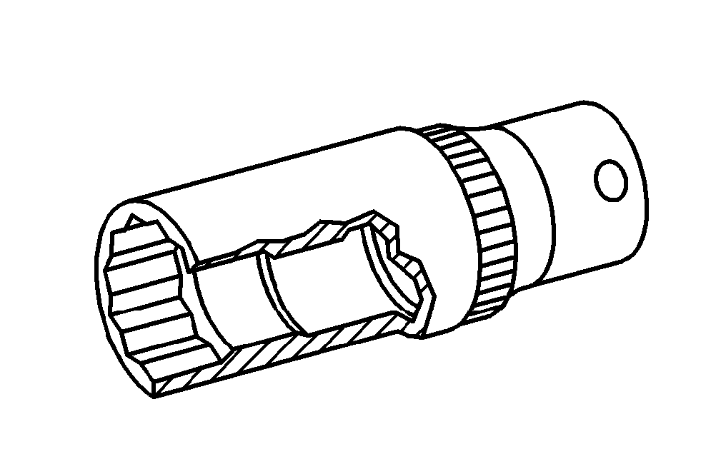
111 589 03 15 00
Retaining pins
Wrench socket
001 589 65 09 00
参照文書
- ar0120d5014sd シリンダ·ヘッド·カバーの脱着
- ar0520d6992sd