Engine | 642.896 ## up to 711427 in model 906 |
with code MP5 (Engine version Euro 5) | |
except code XM0 (Facelift) | |
Engine | 642.896 ## up to 711427 in model 906 |
with code ZU7 (National version for Canada) | |
except code XM0 (Facelift) | |
Engine | 642.896 ## up to 711427 in model 906 |
with code ZU8 (National version for USA) | |
except code XM0 (Facelift) | |
Engine | 642.896 in model 906 |
except code MP5 (Engine version Euro 5) | |
except code XM0 (Facelift) | |
except code ZU7 (National version for Canada) | |
except code ZU8 (National version for USA) | |
Engine | 642.898/992/993 in model 906 |


602 589 03 63 00
Thrust piece
602 589 00 39 00
Riveting tool
602 589 02 63 00
Assembly inserts
602 589 00 98 00
Case

112 589 09 63 00
Assembly inserts

Use the following special tools: assembly inserts, rivet press tool (5), case, assembly inserts and thrust piece (10).
When carrying out work on timing case recess or on cylinder head, protect this with a clean rags to prevent small items dropping down. Parts which have fallen into the timing case recess or cylinder head, must be removed.
Engine damage could occur otherwise.
1 | Insert new riveted link (4) and new middle plate (3) together with centering fork (1) into the ends of the new timing chain (2). The center axle (3) is secured with the centering fork (1). |
D05.10-1142-11
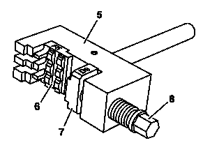
2 | Insert and tighten assembly insert (6) with the imprint F5 into the riveting press tool (5). |
3 | Place assembly insert (7) with the imprint D9 into the rivet press tool (5). |
The assembly insert (7) is able to move on thrust spindle (8) and is loosely mounted. |
D05.10-1141-01

4 | Bottom rivet press tool (5) in such a way that the new timing chain (2) that the assembly insert (7) touches the new riveted link (4) and the centering fork (1) can be pressed out. |
5 | Screw in thrust spindle (8) and press in new riveted link (4) up to the stop and remove centering fork (1). |
Ensure that the new riveted link (4) and assembly insert (7) are aligned. Do not allow the centering fork (1) which is pressed out to drop into the timing case recess. |
6 | Remove thrust spindle (8) and rivet press tool (5). |
7 | Detach assembly inserts (6, 7) from rivet press tool (5). |
D05.10-1140-01

8 | Insert and tighten assembly insert (9) with the imprint F1 into the rivet press tool (5). |
9 | Place thrust piece (10) with the imprint D8 into the rivet press tool (5). |
D05.10-1137-01

10 | Insert new outer plate (11) into the thrust piece (10). |
The new outer plate (11) is held magnetically by the thrust piece (10). |
D05.10-1139-01

11 | Fit on rivet press tool (5) |
The spacer bushing of the assembly insert (9) must lay on the rolls of the timing chain (2) (arrows). |
12 | Screw in thrust spindle (8) on the rivet press tool (5) until there is firm resistance. |
While pressing on ensure that the bolt of the new rivet link (4) in the bores break in the new outer plate (11). |
13 | Remove thrust spindle (8) and rivet press tool (5). |
D05.10-1136-11

14 | Turn thrust piece (10) in the rivet press tool (5) on the rivet profile (arrow). |
D05.10-1135-01

15 | Fit rivet press tool (5) at the center onto one of both timing chain pins of the new riveted link (4) (arrow). |
16 | Tighten thrust spindle (8) of rivet press tool (5) and rivet 1st timing chain bolt of new riveted link (4) . |
17 | Loosen thrust spindle (8) and attach rivet press tool (5) at center on 2nd timing chain bolt of new riveted link (4). |
18 | Tighten thrust spindle (8) of rivet press tool (5) and rivet 2nd timing chain bolt . |
19 | Loosen thrust spindle (8) and remove rivet press tool (5). |
D05.10-1138-11

20 | Check rivetings (arrows) on the new timing chain (2); re-rivet if necessary. |
21 | Remove rag from timing case recess and cylinder head. |
D05.10-1134-01