49-100 Removing, installing exhaust system
Job no. of Job Texts and Work Units or Standard Texts and Flat Rates 49-7000 |
A. Model 201 with engine 601

Hexagon bolt (1) | renew, 20 Nm. |
Front exhaust pipe (2) or front exhaust pipe with oxidation catalytic converter (2a) |
check flanges for signs of damage, tighten evenly. |
Self-locking hexagon nut (3) | renew. |
Self-locking hexagon nut (4) | renew, 20 Nm. |
Sintered sealing ring (5) | examine for signs of damage, ensure correctly seated. |
Retaining clamp (6) | examine for re-use. |
Centre silencer (7) | examine for signs of damage. |
Hexagon bolt (8) | renew. |
Final silencer (9) | examine for signs of damage. |
Side supporting bracket (10) | loosen, fix. |
Hexagon bolt (11) | 20 Nm. |
Washer (12) | |
Rubber pad (13) | examine for signs of wear. |
Large rubber disc (14) | examine for signs of damage. |
Spacer sleeve or small rubber disc (15) | |
Self-locking hexagon nut (16) | renew, 7 Nm. |
Cup spring (17) | renew, ensure correctly installed. |
Rubber ring (18) | examine for signs of damage and wear. |
Hexagon bolt (19) | |
Washer (20) | |
Pipe clip (21) | |
Spring lock washer (22) | renew. |
Hexagon nut (23) | 20 Nm. |
Hexagon bolt (24) | 20 Nm. |
Hanger plate (25) | examine for signs of damage and wear. |
Tensioning plate (26) |
B. Model 124 with engine 601 and 602

Hexagon bolt (1) | renew, 20 Nm. |
Front exhaust pipe without front silencer Model 124.120 (2) | examine flanges for signs of damage, tighten evenly. |
Front exhaust pipe with front silencer or oxidation catalytic converter (2a) with or without spiral hose Model 124.125 |
examine flanges for signs of damage, tighten evenly. (Not available with spiral hose) |
Self-locking hexagon nut (3) | renew. |
Self-locking hexagon nut (4) | renew, 20 Nm. |
Sintered sealing ring (5) | examine for signs of damage, ensure correctly seated. |
Retaining clamp (6) | examine for re-use. |
Centre silencer (7) | examine for signs of damage. |
Hexagon bolt (8) | renew. |
Final silencer (9) | examine for signs of damage |
Side supporting bracket (10) | loosen, fix. |
Hexagon bolt (11) | 20 Nm. |
Washer (12) | |
Rubber pad (13) | examine for signs of wear. |
Rubber disc (14) | examine for signs of damage. |
Rubber ring (15) | |
Self-locking hexagon nut (16) | renew, 7 Nm. |
Cup spring (17) | renew, ensure correctly installed. |
Rubber ring (18) | examine for signs of damage and wear. |
Hexagon bolt (19) | |
Washer (20) | |
Pipe clip (21) | |
Spring lock washer (22) | renew. |
Collar nut (23) | |
Hexagon bolt (24) | 20 Nm. |
Hanger plate (25) | examine for signs of damage and wear. |
Tensioning plate (26) | |
Hexagon nut (27) | 20 Nm. |
Note
Engine 601.912
The coating quantity (platinum) of the catalytic converter can be reduced as a result of reducing the formation of sulphate.
Production breakpoint: as of May 1993
Model | Engine | Chassis ident. end no. |
124.120 | 601.912 | B990322 |
C. Model 124 with engine 603

Hexagon bolt (1) | renew, 20 Nm. |
Front exhaust pipe front silencer or oxidation |
examine flanges for signs of damage, tighten evenly and fit spiral hoses free of stress. |
Self-locking hexagon nut (3) | renew. |
Self-locking hexagon nut (4) | renew, 20 Nm. |
Sintered sealing ring (5) | examine for signs of damage, ensure correctly seated. |
Retaining clamp (6) | examine for re-use. |
Centre silencer (7) | examine for signs of damage. |
Hexagon bolt (8) | renew. |
Final silencer (9) | examine for signs of damage. |
Side supporting bracket (10) | |
Hexagon bolt (11) | 20 Nm. |
Washer (12) | |
Rubber pad (13) | examine for signs of wear. |
Rubber disc (14) | examine for signs of damage. |
Rubber ring (15) | |
Self-locking hexagon nut (16) | renew, 7 Nm. |
Cup spring (17) | renew, ensure correctly installed. |
Rubber ring (18) | examine for signs of damage and wear. |
Hexagon bolt (19) | |
Washer (20) | |
Pipe clip (21) | |
Spring lock washer (22) | renew. |
Collar nut (23) | |
Hexagon bolt (24) | 20 Nm. |
Hanger plate (25) | examine for signs of damage and wear. |
Tensioning plate (26) | |
Hexagon nut (27) | 20 Nm. |
The description which follows does not cover removal and installation of the exhaust system to the full extent, but deals only with particularly important points to which attention requires to be paid when removing and installing or partially renewing the exhaust system, e.g. the final silencer with push-in joint.
Removal
-------------------------------
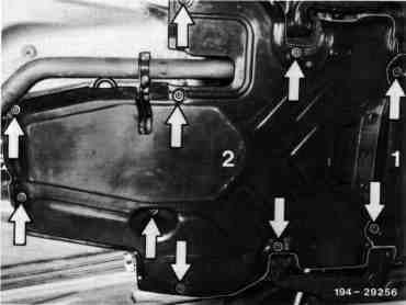
1 Detach rear section of noise capsule when working on the front exhaust system.

2 Examine hanger parts for re-use, renew if necessary.
3 Before installing the exhaust system, ensure that the flange to the exhaust manifold is not twisted; align flange if necessary. Clean combustion residues off tapered connector pieces of pipes and centered sealing rings (2, 5 and 22), if necessary, with emery cloth.
Installation
-------------------------------
Renewing final silencer.
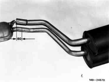
4 Position new final silencer with plug-in joint precisely over removed system and mark length of pipe of new final silencer on removed system.
Cut through the pipe 80 mm away from the mark (tolerance minus 10 mm) in the direction of final silencer to obtain an insertion depth of
70-80 mm.
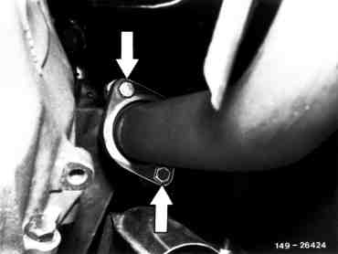
5 Always renew self-locking hexagon nut.
6 Tighten the flanged joint to the manifold evenly. Tigthtening torque of self-locking hexagon nuts 20 Nm.
Models 124.120/125
Model 201.1
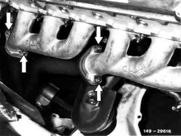
Model 124.130

Caution!
When installing the front exhaust system to the manifold, do not allow the spiral hoses to be tensioned by the weight of the system. Use the side mounting brackets on the transmission as a support (arrow).
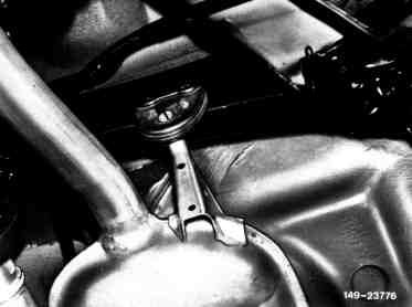
7 Install rear exhaust system with centre and final silencers, at the same time attaching the exhaust system to the rubber hanger at the rear axle support.
8 Install sintered sealing ring (5) at the flanged joint and ensure it is correctly seated. Tightening torque of self-locking hexagon nuts 20 Nm.
2 Front exhaust pipe
5 Sintered sealing ring
6 Self-locking hexagon nut
7 Hexagon bolt
18 Flange
22 Rear exhaust pipe
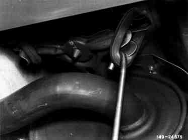
9 Use a suitable hook to attach rubber rings to the rear silencer.
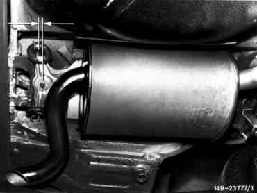
10 Install rear silencer in such a way that the retaining clamps of the rear silencer are positioned approx. 10 mm ahead of the brackets on the frame floor to ensure that the system is correctly installed when the exhaust expands (arrows).
Note
This relates only to silencers as repair version with plug joint between centre and rear silencers.
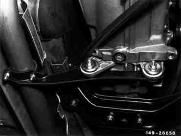
11 Install side mounting bracket of exhaust free of stress. Tightening torque of self-locking hexagon nuts at tensioning clamp 7 Nm, of hexagon bolts of side mounting bracket on transmission 20 Nm.
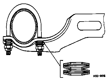
Note
Install 4 cup springs on each side of retaining clamp in such a way that the convex ends are apart (as shown in illustration).
12 Run engine and examine exhaust system for leaks.
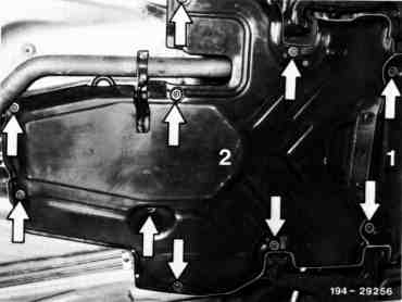
13 Install noise capsule.
D. Model 202 with engine 601.913

Lower part of noise encapsulation | unscrew, screw on. |
Flanged joint of exhaust manifold - oxidation catalytic convertor of front exhaust system |
separate, connect. To do this, unscrew bolts (1), screw in. |
Nuts (10/2) at threaded plate (10/1) | unscrew, screw on. Tightening torque 20 Nm as a reference value. |
Threaded plate (10/1) | remove, examine, replace if necessary, insert. |
Rubber pads (7/1, 9/1) | detach, examine, replace if necessary, attach. |
Complete exhaust system | take off, insert. Note If necessary, clean all connection points of combustion and corrosion residues with emery cloth. |
Leak tightness of all connection points | check with engine running. |
Disposing of catalytic convertors
Catalytic convertors must not be disposed of as scrap. The catalytic convertor contains valuable noble metal which must be recycled to the production process.
Details regarding return addresses and exchange prices can be obtained from the brochure
"Information Parts and Accessories".