07.1-103 Checking electronic idle speed control
Job no. of Job Texts and Work Units or Standard Texts and Flat Rates 07-2005 and 2006 |
Engines without test coupling (X92)
(Engines with test coupling (X92) see 07.1-105 Checking ARA and/or ELR).

Digital tester (001) and pulse generator (021) | connect, disconnect. |
Control | check for easy operation. |
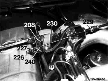
Idle speed stop on Bowden cable (230) | check, the spring retainer (226) must contact the compression spring (227) without preload. |
Overvoltage protection (K1 or K1/1) and fuse | check, measure voltage between jacks 9 and 11 of the control unit coupling, set value approx. |
Engine | run to 60-80 °C coolant temperature. |
Pull double coupling off electromagnetic actuator (Y22) and refit (at least for 3 s) |
engine speed increases briefly. |
Adjusting basic idle speed on injection pump | pull plug of electromagnetic actuator (Y22). |
Speed sensor (L3) on coupling (L3x) | check, resistance 0.4-2.5 kW, engine at idle speed voltage > 4 V AC. |
Coolant temperature sensor (B11/1) | check, set value +20 °C 2.2 - 2.8 kW. |
Electrical activation of the electromagnetic |
check, engine idling, set value approx. 12 V. |
Test and adjusting values
Engine | Idle speed 1/min | |
with control | without control | |
601.91 | 72020 | 66040 |
602.91 | 68020 | 62040 |
603.912 und 603.9131) | 63020 | 58040 |
603.9132) | 68020 | 62040 |
1) Automatic transmission
2) Manual transmission
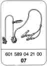
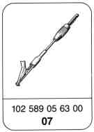
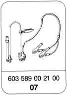
Special tools
Commercially available tools
Multimeter | e.g. Sun, DMM-5 |
Digital tester | e.g. Bosch, MOT 002.01 |
Note
Electrical wiring diagrams see
job no. 07.1-400.
Testing jobs
-------------------------------
Connect digital tester (001) and pulse
generator (021).
Check control for easy operation and condition.
Check idle speed stop on Bowden cable (230).
The spring retainer (226) of the Bowden cable (230) in idle speed position must contact the compression spring (227) without preload.
Run engine to 60-80 °C coolant temperature.
Checking overvoltage protection (K1 or K1/1)


Switch on ignition, pull off control unit (N8 or N8/1) and check voltage between the jacks (9 and 11).
Display: approx. = 12 V
No
Yes
Check fuse on overvoltage protection. Check activation according to electrical wiring diagram.
End of test
Function check


Engine idling. Pull double coupling (arrow) off ELR electromagnetic actuator (Y22) for at least 3 s and refit. Engine speed increases briefly.
Yes
No
Briefly apply battery voltage (approx. 12 V) to ELR electromagnetic actuator (Y22). Idle speed increases.
Caution!
If battery voltage is applied for longer than 3 s the ELR electromagnetic actuator will be damaged.
Yes
No
Renew electromagnetic actuator (Y22).
Check individual parts.
Engine idling. Pull double coupling of electromagnetic actuator (Y22).
Check idle speed.
Set values:
Engine Idle speed/min
601.91 66040
602.91 62040
603.912+603.913
with automatic transmission 58040
603.913
with manual transmission 62040
Yes
No
End of test

Adjust idle speed by loosening lock nut (arrow).
left = higher
right = lower
End of test
Checking speed sensor (L3)

Renew starter ring gear speed
sensor (L3).
Engine switched off. Remove plug connector (L3x). Connect multimeter and press key "W". Check resistance.
Yes
No
Display: 0.4-2.5 kW

Inspect starter ring gear speed sensor for accumulation of dirt or metal chips, clean if required.
Multimeter connection as above, press key
"V". Run engine at idle speed.
End of test
Yes
No
Display: > 4 V AC
Voltage rises with speed.
Checking coolant temperature sensor (B11/1)


Engine switched off. Remove plug from temperature sensor and measure resistance against ground.
Set values see diagram.
Measure resistance at two temperature measuring points.
Example:
+20 °C = 2.2-2.8 kW
+80 °C = 290-370 W
No
Yes
Renew coolant temperature sensor.
End of test
Measure voltage on 1-pole coupling (arrow) "Ignition" On.
Display: approx. 5 V
End of test
Eliminate line interruption. Renew control unit (N8 or N8/1).
No
Yes
Checking electrical activation of electromagnetic actuator

Engine idling. Remove double coupling (arrow) from electromagnetic actuator (Y22) and measure voltage with multimeter in key "V =".
Display: approx. = 12 V
End of test
Check activation according to electrical wiring diagram, renew control unit (N8 or N8/1) if required.
No
Yes
Documenti citati
- ra07016010001x
- ra07016010002x
- ra07016010003x
- ra07016010105x
- ra070160104a0x
- ra070160104a1x
- ra070160104a2x
- ra070160104a3x
- ra070160104a4x
- ra070160104a5x
- ra070160104a6x
- ra070160104a7x
- ra070160104a8x
- ra070160104a9x
- ra070160104b0x
- ra070160104b1x
- ra070160104b2x
- ra070160104b3x
- ra070160104b4x
- ra070160104b5x
- ra070160104b6x
- ra070160104b7x
- ra070160104b8x
- ra070160104b9x
- ra070160104c0x
- ra070160104c1x
- ra070160104c2x
- ra070160104c3x
- ra070160104c4x
- ra070160104c5x
- ra070160104c6x
- ra070160104c7x
- ra070160104c8x
- ra070160104c9x
- ra070160104d0x
- ra070160104d1x
- ra070160104d2x
- ra070160104d3x
- ra070160104d4x
- ra070160104d5x
- ra070160104d6x
- ra070160104d7x
- ra070160104d8x
- ra070160104d9x
- ra070160104e0x
- ra070160104e1x
- ra070160104e2x
- ra070160104e3x
- ra070160104e4x
- ra070160104e5x
- ra0701601a010x
- ra0701601a015x
- ra0701601b010x
- ra0701601b015x
- ra0701601c010x
- ra0701601c015x
- ra0701601d010x
- ra0701601e010x
- ra0701601f010x
- ra0701601g010x
- ra0701601h010x
- ra0701601i010x
- ra0701601j010x
- ra0701601k010x
- ra0701601l010x
- ra0701601m010x
- ra0701601n010x
- ra0701601o010x
- ra0701601p010x
- ra0701601pr02x
- ra0701601q010x
- ra0701601r010x
- ra0701601ta00x