07.1-015 Function exhaust gas recirculation
The vehicles listed in the table below were equipped with an electronically/pneumatically-controlled exhaust gas recirculation system and oxidation catalytic convertor as of the respective model year.
National version
Engine | Model year/National version | ||||||
1984 | 1985 | 1986 | 1987 | 1988 | 1989 | 1990 | |
601.911 | | | | ||||
601.912 | | | | ||||
601.921 | | | |||||
602.911 | | | | ||||
602.912 | | | |||||
603.912 | | | | ||||
Basic and national version
601.911 601.912 | 1991 | 1992 Std with code 62/0 as of 06/92 | |
601.913 | Std with code 62/0 as of 06/93 | ||
602.91 | 1991 | 1992 Std with code 62/0 as of 06/92 | |
603.91 | 1991 | 1992 Std with code 62/0 as of 06/92 | |
C. Function

Catalytic convertor
Engines 601.91, 602,91, 603.91 Standard as of 06/90 are available with an oxidation catalytic convertor as optional equipment with code no. 62/0 (cannot be retrofitted).
The oxidation catalytic convertor is installed in the front exhaust system.
The catalytic convertor housing and the pipe outlets are made of stainless steel.
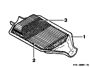
The noble metal coating of the catalyst activates post-oxidation in the exhaust gas as a result of which hydrocarbons (HC) and carbon monoxide (CO) are converted to water (H2O) and carbon dioxide (CO2). As a result of this process the emitted particulate mass is also reduced as the deposited elements are reduced.
1 Housing
2 Wire mesh
3 Monolith
Vacuum control valve (65)
The vacuum control valve is attached to the injection pump and connected to the control lever by means of a driver. With supply vacuum available (central connection) it modulates a pressure with dropping characteristic with increasing load.

The vacuum control valves have a different characteristic depending on the engine and transmission design. They are identified by differently coloured sealing caps and must not be confused (see 07.1-170).
65 Vacuum control valve
A Control line
B Suction line

Vacuum transducer (123)
(only with automatic transmission)
Attached to the unit wall.
The pressure modulated by the vacuum control valve is converted in the vacuum transducer (123) for use in the exhaust gas recirculation system. By way of the change-over valves (Y27 and Y28) the exhaust gas recirculation valve and the vacuum control flap are activated. The modulated pressure can be continuously adjusted with the adjusting screw (124) - below the red protective cap - by approx. 100 mbar (except USA as of model year 1986).
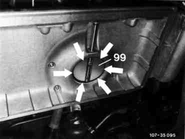
Air guide housing with vacuum control flap (99)
A pneumatically actuated vacuum control flap (99) is provided in the air guide housing in order to increase the vacuum in the intake pipe. During engine operation with exhaust gas recirculation the vacuum control flap closes off the fresh air duct.
A minimum opening (arrow) between the vacuum control flap (99) and the air guide housing is maintained in a closed condition.
Note
The linkage on the vacuum unit for the vacuum control flap (99) may not be actuated manually.

Mechanical pressure control flap (99) with pneumatic control group, temperature-dependent >40 °C
Engine 601.911/912 up to 01/93
Engine 602, 603
The exhaust gas recirculation is optimised by a mechanical actuation of the pressure control flap (99), thus improving the degree of the exhaust gas recirculation rate.
The pressure control flap (99) is always approximately 35° open in its initial setting (at idle speed).

When the coolant temperatures are > 40 °C between 1000 50/min and 2500 50/min the pressure control flap is pneumatically closed via the thermovalve (180) and is opened again mechanically via the accelerator depending on the load condition.
The pressure control flap is open at full throttle.

It became necessary to introduce a connecting rod (200) at the vacuum unit for the pressure control flap (due to the mechanical actuation of
the pressure control valve (99)).
The vehicles listed in the table below have been fitted with a mechanical/pneumatic pressure control flap from the appropriate model year.
Test and adjustment data
Engine | Transmission | Model year/National version |
1990 | 1991 | ||
601.91 | manual | | Standard with code 62/0 |
601.91 | automatic | - | Standard with code 62/0 |
603.91 | manual automatic | - | |
1) automatic transmission
2) manual transmission

Exhaust gas recirculation valve
The exhaust gas recirculation valve is screwed into the side of the cylinder head. It is connected with the exhaust and the intake manifolds by way of the exhaust gas recirculation line.
The exhaust gas recirculation valve is activated by the modulated vacuum from the vacuum control valve and opens depending on the load condition.

Notes
To reduce the noise level, the exhaust gas recirculation valve (ARF) is provided with a smaller ventilation shaft (a) and a shaped valve seat (b). Tulip-chaped fitting for vacuum connection.
A Previous version
B Present version
Production breakpoint: as of June 1991
Model | Engine | Engine end no. Automatic transmission |
124.120 | 601.912 | 015602 |
201.122 | 601.911 | 028127 |
Production breakpoint: as of July 1991
Model | Engine | Engine end no. Manual transmission |
124.120/180 | 601.912 | 169876 |
124.125/185 | 602.912 | 195133 |
124.130/190 | 603.912 | 072851 |
201.122 | 601.911 | 375017 |
201.126 | 602.911 | 105180 |
Production breakpoint: as of October 1991
Model | Engine | Engine end no. Automatic transmission |
124.120 | 601.912 | 016302 |
124.105/106/125/127/185 | 602.912 | 031684 |
124.130/190 | 603.912 | 050567 |
201.122 | 601.911 | 028776 |
201.126 | 602.911 | 020758 |
Engines 601.911/912, 602.911/912
Cast valve (was steel). Reason: cost and weight reduction.
Production breakpoint: as of December 1992
Model | Engine | Engine end no. Manual transmission |
201.122 | 601.911 | 417481 |
Production breakpoint: as of February 1993
Model | Engine | Engine end no. Manual transmission | Engine end no. Automatic transmission |
124.105/106/125/127/185 | 602.912 | 235709 | |
124.120 | 601.912 | 194779 | 019826 |
201.122 | 601.911 | 031040 | |
201.126 | 602.911 | 122345 | |
Engine 601.912/913
EGR valve modified.
Production breakpoint: as of May 1993
Model | Engine | Engine end no. Manual transmission |
124.120 | 601.912 | 199557 |
Production breakpoint: as of May 1993
Model | Engine | Engine end no. Manual transmission | Engine end no. Automatic transmission |
202.120 | 601.913 | 001194 | 000042 |

Control unit (N37 and N37/2)
This is installed behind the battery. Battery voltage is available on the control unit EGR
(N37 or N37/2) after the ignition has been switched on. Minimum working voltage approx. 11 V.
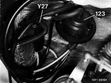
Electrical change-over valve (Y27)
This admits vacuum for the exhaust gas recirculation in certain operating conditions. The activation is by way of the control unit EGR
(N37 or N37/2) as a function of coolant temperature and engine speed as well as speed and load-dependent on the microswitch (only with manual 5-speed transmission).
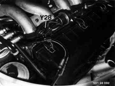
Electrical change-over valve (Y28)
This admits the vacuum for the vacuum control flap under certain operating conditions. The activation is by way of the control unit EGR
(N37 or N37/2) as a function of coolant temperature and engine speed as well as dependent on speed and load via the microswitch (S27/4).
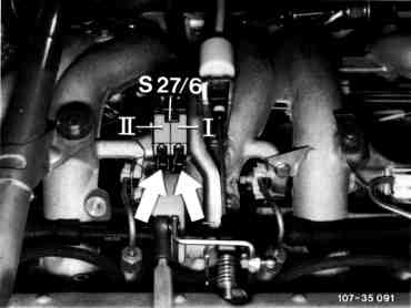
Microswitch (S27/6)
Microswitch I
Switches off the exhaust gas recirculation and the AC compressor before full load (AC compressor only if climate comfort control is operative).
Microswitch II
Switches off the vacuum control flap before reaching full load.

Coolant temperature switch 97° and
100 °C (S25/1, S25/4, S25/9)
For thermal protection of the engine the temperature switch switches off the exhaust gas recirculation via the control unit EGR (N37 or N37/2) from a coolant temperature of approx. 100 °C.
Model 124, 201
Engine 601
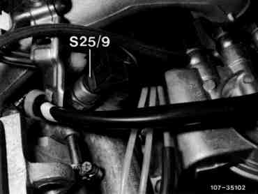
Model 124 Engine 603
Engine 601

Model 201 Engine 601

Model 201 Engine 602

Temperature switch 25 °C (S25/7)
except
Model year 1984 engine 601.92
Up to a temperature of 25 °C the exhaust gas recirculation is switched off via the temperature switch (S25/7).
Engine 601.912, 602.91

Engine 603.91

Starter ring gear speed sensor (L3)
This is attached to the flange of the transmission. The speed sensor (L3) consists of a magnetic core and a coil. It registers the engine speed, passing it on to the control unit ARF (N37 or N37/2) in form of an AC voltage.
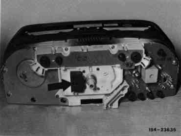
Hall-effect speed sensor (B6)
(only with manual transmission)
The vehicle speed is taken off the speedometer by the Hall-effect speed sensor (arrow). At a speed above 87 km/h the exhaust gas recirculation is switched off by the control unit ARF (N37 or N37/2).
Exhaust gas recirculation
Engine 601.911/912 up to 01/93
Engine 602, 603
Exhaust gas recirculation is performed if the following requirements are met: Engine speed between 100050/min and 295050/min Coolant temperature between 25 °C and 100 °C, engine 601, 97 °C, engine 602 and 603. Speed below 85 km/h (only 5-speed manual transmission). Road speed signal not applicable for engine 601 with code 960 and 830, model year 1991 Accelerator pedal not in full throttle position as the ARF valve is closed via the microswitch just before full throttle. Pressure control flap closed between 100050/min and 250050/min, except engine 601.92 and engine 601 with code 620, which is closed between 1200 50/min and 295050/min. The ARF (N37 or N37/2) detects imput signals from Engine speed Road speed (only 5-speed manual transmission) Temperature Load (accelerator pedal position) | It supplies a voltage signal to the switch-over valves (Y27) and (Y28). Supply vacuum exists at the vacuum control valve (65) and at the vacuum transducer (123). The vacuum control valve (65) supplies a modulated vacuum to the vacuum transducer (123). This controls the vacuum from the vacuum control valve in accordance with the load condition. The ARF valve and the pressure control flap are actuated with this controlled vacuum. The pressure control flap is closed from 100050/min up to 250050/min, which increases the exhaust gas recirculating rate. Notes As of model year 1990 mechanical pressure control flap (99) with pneumatic control unit, operated temperature-dependent via thermovalve > 40 °C. As of April 1991 the piston ground cooling is no longer fitted to vehicles with exhaust gas recirculation. |
Exhaust gas recirculation
Engine 601.912 as of 02/93
Engine 601.913 as of 06/93

The exhaust gas recirculation and the pressure control flap are controlled by the ARF control unit (N37) via the ARF switch-over valves (Y27) and pressure control flap (Y28).
Exhaust gas recirculation is performed if the following requirements are met:
From about 100 seconds after engine start
Engine speed between 105050/min and 320050/min
Up to 10° before full throttle stop (injection pump control lever)
The pressure control flap operates:
From approx. 150 secondes after engine start
Engine speed between 125050min and 250050/min
Up to 15° before full throttle
This procedure is repeated each time the engine is started and is independent of the coolant tempertaure.
Note
The 40 °C thermovalve and the 25 °C and
100 °C termperatue switches are no longer fitted (see Function diagram exhaust gas recirculation).
Block diagram exhaust gas recirculation model 124, 201
Engine speed
TD signal
Hall-effect speed sensor
Speed (only manual 5-speed transmission)
Microswitch
Load shut-off
Control unit (N37/2)
Coolant temperature
as of 25 °C up to 97 °C
or 100 °C
Voltage signal
Voltage signal
Vacuum pump
(supply)
Vacuum control valve (65)
Pneumatic vacuum transducer (123)
Controlled vacuum
Electrical change-over valve (Y27)
ARF valve (60)
Controlled vacuum
Electrical change-over valve (Y28)
Vacuum control flap (99)
Block diagram exhaust gas recirculation with mechanical/pneumatic pressure control flap as of 09/89 model 124, 201
1) 15° before full throttle from model year 1990
2) Speed signal deleted on engine 601 with code 960 and 830 as of model year 1991
Engine speed
TD signal
Hall-effect speed sensor 2)
Speed (only manual 5-speed transmission)
Microswitch
Load shut-off 1)
Control unit (N37/2)
Coolant temperature
as of 25 °C
up to 97 °C engine 602, 603
100 °C engine 601
Voltage signal
Voltage signal
Vacuum pump
(supply)
Vacuum control valve (65)
(controlled vacuum)
Accelerator pedal position
Electrical change-over valve (Y27)
ARF valve (60)
Electrical change-over valve (Y28)
Vacuum control flap (99)
Thermovalve
40 °C
Block diagram exhaust gas recirculation with mechanical/pneumatic pressure control flap in
model 124 as of 02/93 and model 202 as of 06/93
Engine speed
TD signal
ARF 10° before full load
Load cut-off
Control unit
(N37/2)
Voltage signal
Voltage signal
Vacuum pump
(supply)
Vacuum control valve (65) (controlled vacuum)
Accelerator pedal position
Electric switch-over valve (Y27)
Exhaust gas recirculation valve (60)
Electric switch-over valve/
pressure control flap (Y28)
Pressure control flap vacuum unit (99)
Pressure control flap 15° before full load
Vacuum transducer only for automatic transmission
Documenti citati
- ra07016010001x
- ra07016010002x
- ra07016010003x
- ra07016010170x
- ra0701601a010x
- ra0701601a015x
- ra0701601b010x
- ra0701601b015x
- ra0701601c010x
- ra0701601d010x
- ra0701601e010x
- ra0701601f010x
- ra0701601g010x
- ra0701601h010x
- ra0701601i010x
- ra0701601j010x
- ra0701601k010x
- ra0701601l010x
- ra0701601m010x
- ra0701601n010x
- ra0701601o010x
- ra0701601p010x
- ra0701601pr02x
- ra0701601q010x
- ra0701601r010x
- ra0701601ta00x