03-4352 Removing crankshaft, mounting in bearings and installing
Preceding work: Engine removed (01-2200). Oil sump removed (01-7500). Timing case cover removed (01-8000). Pistons removed (03-7081). Oil pump removed (18-6023). Oil filter holder removed. |

1 Hexagon bolt 2 Kidney-shaped cover 3 Gasket 4 Timing case 4a Lower section of timing case 4b Hexagon bolt (on divided crankcase) 4c Hexagon bolt (on divided crankcase) 5 Adapter 6 Gasket 7 Hexagon bolt 8 Thrust washer 9 Hexagon bolt 10 Securing bolt 11 Injection timer 12 Shim 13 Parallel key 14 Crankshaft 15 Conrod bearing shells 16 Main bearing shells 17 Fitted bearing shells 18 Crankshaft bearing cap 18a Dowel pins | coat with Hylomar SQ 32M sealant. replace. coat contact surface with Curil T sealant coat with Hylomar SQ 32M sealant. replace. replace, coat with Curil T sealant. 60 Nm. 35 Nm. 300 Nm. See Data "A". Hardness drop tester 000 589 20 21 00 Dial gauge 001 589 53 21 00 Gauge stand 363 589 02 21 00 see Operation no. 03-8312. See Data "B". Dial gauge 001 589 53 21 00, coat contact surfaces with engine oil. See Data "B". Dial gauge 001 589 53 21 00, coat contact surfaces with engine oil. Projection 9.5 mm. |
19 Main bearing bolt 20 Crankshaft bearing cap 21 Locking pin 22 Fabric seal 23 Flywheel housing 24 Hexagon bolt 25 Hexagon bolt | 1st stage 80 to 90 Nm, coat contact surfaces with Dirko Transparent sealant. replace, projection 0.8 to 1.1 mm is distributed half each to crankcase and crankshaft bearing cap. Coat with universal grease. |
Data "A" crankshaft
Axial clearance of crankshaft Fitted bearing 0.190 to 0.290
Conrod bearing 0.100 to 0.400
Radial clearance of crankshaft Main bearing 0.042 to 0.108
Fitted bearing 0.050 to 0.108
Conrod bearing 0.041 to 0.100
Permissible out-of-roundness of main Limit 0.01
and conrod bearing journals
Permissible conicity Main bearing journal 0.01
Conrod bearing journal 0.005
Permissible lateral runout Crankpin 0.02
Fillet radii Main bearing journal 3.5 to 4.0
Fitted bearing 4.0 to 4.5
Hardness of crankshaft and conrod bearing journals (Rockwell hardness) 53 to 59 HRC
after damage to bearings and in the case of severe bearing wear,
over two thirds of the circumference min. 46 HRC
Standard | Deviation 0.1 | Deviation 0.25 | Deviation 0.5 | Deviation 0.75 | Deviation 1.0 | |
Diameter of | 88.010 87.990 | 87.910 87.890 | 87.760 87.740 | 87.510 87.490 | 87.260 87.240 | 87.010 86.990 |
Width of crankpins | 32.062 32.000 - - | 32.062 32.000 - - | 32.062 32.000 32.362 32.300 32.562 32.500 | 32.062 32.000 32.362 32.300 32.562 32.500 | 32.062 32.000 32.362 32.300 32.562 32.500 | 32.062 32.000 32.362 32.300 32.562 32.500 |
Diameter of | 60.015 60.995 | 59.915 59.895 | 59.765 59.745 | 59.515 59.495 | 59.265 59.245 | 59.015 58.995 |
Width of | 38.130 37.930 | for repairs max. 38.330 |
Data "A" crankshaft
Permissible imbalance 30 cmp
Camber Main bearing journal 0 to 0.004
Conrod bearing journal 0 to 0.04
for rep. max.
Data "B" (Main bearing and fitted bearing)
Standard | Deviation 0.1 | Deviation 0.25 | Deviation 0.5 | Deviation 0.75 | Deviation 1.0 | |
Diameter of main bearing | 88.098 88.052 | 87.998 87.952 | 87.848 87.802 | 87.598 87.552 | 87.348 87.302 | 87.098 87.052 |
Diameter of fitted bearing | 88.098 88.060 | 87.998 87.960 | 87.848 87.810 | 87.598 87.560 | 87.348 87.310 | 87.098 87.060 |
Width of fitted bearing | 31.810 31.740 | 31.810 31.740 | 31.810 31.740 | 31.810 31.740 | 31.810 31.740 | 31.810 31.740 |
- | - | 32.110 32.040 | 32.110 32.040 | 32.110 32.040 | 32.110 32.040 | |
- | - | 32.310 32.240 | 32.310 32.240 | 32.310 32.240 | 32.310 32.240 |
Basic bore diameter | 93.022 93.040 93.000 92.970 |
Data "C" (Conrod bearing shells)
Standard | Deviation 0,1 | Deviation 0,25 | Deviation 0,5 | Deviation 0,75 | Deviation 1,0 | |
Diameter of bearing bore | 60.095 60.056 | 59.995 59.956 | 59.845 59.806 | 59.595 59.556 | 59.345 59.306 | 59.095 59.056 |



Special tools
Note
The previous locating plate part no. 352 589 01 31 00 can be returned for conversion to:
Ludwig Weyland GmbH
Lotschstr. 11
76829 Landau

Removing
1 Unscrew main bearing bolts (19).
2 Slacken crankshaft bearing cap (18, 20) with a plastic hammer and remove.

Note
The crankshaft bearing caps and the bearing shells of the main bearings must be marked in accordance with the fitting order in order to avoid mix-ups.

3 On divided timing case:
3.1 Dismantle and remove lower section of timing case (4a).

4 On one-piece timing case:
4.1 Remove kidney-shaped cover (2) on timing case and remove gasket (3).

4.2 Crank engine in direction of rotation until the marking of the camshaft and crankshaft are aligned.
Note
The tooth of the crankshaft gear marked with "1" must be located between the teeth of the injection timer which are also marked with "1-1".

4.3 Mark injection pump gear relative to timing case.
4.4 Remove injection pump (07-8410). Remove O-ring.

4.5 Unscrew securing bolt (10) for injection timer (11).

4.6 Pull off injection timer (11) and parallel key (13).

4.7 Remove shim (12) and thrust washer (8) for camshaft.
4.8 Remove timing case (4). Remove gasket (6).

5 Lift crankshaft (14) out of crankcase.
Note
On flywheel housing which is closed underneath:
Remove flywheel (03-8001) and remove flywheel housing (23).

6 Take main bearing shells (16, 17) out of the crankcase and out of the main bearing caps and mark.

7 Remove fabric seal (22) and locking pin (21) from crankcase and crankshaft bearing cap (20).
8 Check all parts for wear and tear.

Bearings
Note
The main bearing shells of the crankshaft are factory-supplied ready for installation. It is not permitted to perform any machining work on the bearing shells.
1 Use a shammy leather to clean the bearing points in the crankcase and in the crankshaft bearing caps.

2 Measure bearing journals of the crankshaft. See data "A" for dimensions.
3 Insert bearing shells into the crankcase and into the crankshaft bearing caps in the correct order. Ensure that the locking lugs of the bearing shells are properly located in the slots and in the basic bores.

Note
The main bearing shells in the crankcase are provided with an oil bore and must be aligned with the lubricating bore in the crankcase (arrows).
4 Fit crankshaft bearing caps (18, 20) onto the crankcase. Pay attention to the marking.
Note
- Fit the crankshaft bearing cap with cylindrical or tapered dowel pin. The two versions of the dowel pin must not be mixed up.

- Replace the tapered dowel pins (18a) only in pairs. Install new dowel pins (18a) with the cylindrical half in the crankshaft bearing caps. Projection dimension "A": 9.5 mm.

5 Tighten main bearing bolts (19),
1st stage 80 to 90 Nm,
2nd stage 90° to 100° angle of rotation.

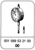
6 Attach dial gauge to hole gauge. Set 50 - 100 mm diameter hole gauge with 75 - 100 mm diameter micrometer to the zero size of the main bearing bore.
Dial gauge 001 589 53 21 00

7 Measure main bearing bore with the set 50 - 100 mm dia. hole gauge at three points (vertical and at about 30° above and below the separation points).
Note
The measurements must conform to the figures stated in data "B".

8 Remove crankshaft bearing caps (18, 20) again and remove the fitted and main bearing shells from the crankcase.

Bearings and installation
1 Use a wire brush to clean the oil galleries of the crankshaft (14) and blow out.
2 Blow out oil galleries from the oil pump end.
3 Use a chamois leather to clean crankshaft bearing journals, main bearing shells and bearing seats.

4 Check the crankshaft and conrod bearing journals with a hardness drop tester. See data "A" for hardness.
Note
A conversion table is enclosed with the hardness drop tester.
Hardness drop tester 000 589 20 21 00

5 Use an aluminium drift to insert locking pin (21) in the crankcase and in the crankshaft bearing cap (20).
Note
Tip of locking pin faces out of the hole and must not be damaged.

6 Insert new fabric seal (22) exactly into the locating plate.
Note
Both ends of the fabric seal (22) must be making contact with the locating plate.
Locating plate 352 589 02 31 00

7 Fit on locating plate and press fabric seal into the crankcase. Remove locating plate.
Locating plate 352 589 02 31 00
8 Cutting fabric seal to the correct length
Note
- The projection (overlap) of 0.8 to 1.1. mm is distributed half each to the crankcase and to the crankshaft bearing cap.
- After installing the crankshaft bearing cap, there must be an overlap of the two fabric seals of 0.8 to 1.1 mm.

8.1 To ensure that an exact overlap is achieved, select an appropriate valve gauge and fit onto the crankcase as a spacer gauge.
8.2 Make cuts in the fabric seal at 3 sides (arrows), before finally cutting to length to prevent it fraying when it is finally cut to length.
8.3 Start cutting off fabric seal with a sharp knife at the end which has not yet been cut.

9 Insert new, second fabric seal (22) into the locating plate. Mount locating plate on the crankshaft bearing cap and press in fabric seal (22). Remove locating plate.
Locating plate 352 589 02 31 00
10 Cutting fabric seal to correct length.
Note
- The projection (overlap) of 0.8 to 1.1 mm is distributed half each to the crankcase and to the crankshaft bearing cap.
- After installing the crankshaft bearing cap, there must be an overlap of the two fabric seals of 0.8 to 1.1 mm.

10.1 To ensure that an exact overlap is achieved, select an appropriate valve gauge and fit onto the crankcase as a spacer gauge.
10.2 Make cuts in the fabric seal at 3 sides (arrows), before finally cutting to length to prevent it fraying when it is finally cut to length.
10.3 Start cutting off fabric seal with a sharp knife at the end which has not yet been cut.

11 Coat fabric seals (22) in crankcase and in the crankshaft bearing cap (20) with hot bearing grease.
12 Install crankshaft bearing cap with fabric seal as a check and tighten bolt to 90 Nm (initial torque).
13 Remove crankshaft bearing cap again and check fabric seals at the joint for loose or compressed fibers; cut off with a sharp knife, if necessary.
14 Insert main bearing shells into the crankcase and into the crankshaft bearing caps in the correct order. Ensure that the locking lugs of the main bearing shells are properly located in the slots and in the basic bores.
Note
The main bearing shells in the housing are provided with an oil bore and must be aligned with the lubricating bore in the crankcase (arrows).

15 Coat slot and contact surface at the rear crankshaft bearing cap (20) with Dirko Transparent sealant.
Note
- The surfaces to be coated with the sealant must be free of grease.
- The contact surfaces of the fabric seals must not be coated with sealant.
16 Oil contact surface of the main bearing shells with engine oil.

17 Insert crankshaft (14) into the main bearing shells.

Note
On the divided timing case ensure that the tooth of the crankshaft gear marked with "1" is located between the teeth of the injection timer which is also marked with "1-1".

18 Measure length of shank of the main bearing bolts (19).
Note
The main bearing bolts (19) may be re-used up to a maximum shank length of 123.0 mm.

19 Fit on crankshaft bearing caps (18, 20) with bearing shells. Ensure that the markings of the bearings that go with them are aligned.
Note
- Fit crankshaft bearing cap with cylindrical or tapered dowel pins.
The two versions of the dowel pins must not be mixed up.
- Replace tapered dowel pins (18a) in the crankshaft bearing caps only as a pair. Install new dowel pins (18a) with the cylindrical half into the crankshaft bearing caps, projection dimension "A" 9.5 mm.

20 Tighten main bearing bolts (19),
1st stage 80 to 90 Nm,
2nd stage 90° to 100° angle of rotation.

21 Attach dial gauge and gauge stand to timing case or crankcase. Measure axial clearance of crankshaft (fitted bearings) 0.190 to 0.290 mm.
Dial gauge 001 589 53 21 00
Gauge stand 363 589 02 21 00

22 On divided timing case:
22.1 Coat contact surfaces of lower section of timing case (4a) with Curil T sealant.
22.2 Coat hexagon bolt M840 (4b) on thread with Hylomar SQ 32M sealant.
22.3 Screw on lower section of timing case with hexagon bolts M840 (4b) and M822 (4c) to timing case.

23 On one-piece timing case
23.1 Fit timing case (4) with new gasket (6) onto crankcase.
Note
- Coat engine end of gasket (6) with Curil T sealant.
- Identification of adapter (5):
OM 364 "4"; OM 366 "6".
23.2 Install new one-piece adapter (5) in timing case (4) (oil return of belt-driven air compressor).

23.3 Tighten hexagon bolts (7) to 60 Nm.
23.4 Install thrust washer (8) for camshaft. Tighten hexagon bolts (9) to 35 Nm.
23.5 Slide on shim (12).
23.6 Install injection timer (11) and parallel key (13).
Note
- Backlash 0.070 to 0.180 mm.

- The tooth of the crankshaft gear marked with "1" must be located between the teeth of the injection timer which is also marked with "1-1". The markings must be in line with the center of the two gears.
23.7 Tighten securing bolt (10), 300 Nm.
23.8 Install injection pump (07-8410). Install new O-ring. Tighten hexagon bolt to 45 Nm.
Note
The marking of the injection pump gear points toward the marking on the timing case.
23.9 Check start of delivery and adjust (07-8234).
23.10 Install kidney-shaped cover (2) with new gasket. Coat hexagon bolts (1) with Hylomar SQ 32M sealant and tighten.
24 Installing flywheel housing (closed version)
24.1 Install flywheel (03-8001).
Documenti citati
- bb0040p022302a Oli motore prescritti per autovetture, veicoli commerciali (servizio assistenza) - Panoramica
- bb0040p026700a Grassi multiuso (classe 2 NLGI)
- ra00333640002x
- ra00333640004x
- ra00333640005x
- ra00333640010x
- ra00333640901x
- ra01333642200x
- ra01333647500x
- ra01333648000x
- ra03333646311x
- ra03333647081x
- ra03333648001x
- ra03333648312x
- ra07333648234x
- ra07333648410x
- ra18333646023x