Modification: Model 124 with engines 104.942 and 104.992 included
Installation Instructions
Coolant Pre-heater 20.1
Model 124
To prevent the engine from cooling off completely at low ambient temperatures, an electric coolant Pre-heater is available for retrofitting. The unit, which can both heat the engine coolant and keep it warm, is installed in a drain plug bore in the engine block. An electrical plug is provided for connecting the coolant Pre-heater to standard household current supply. The unit's power consumption is 500 W at a voltage of 220 V (115V optional).
The installation instructions are subdivided into the following sections:
A. Procedure
a) Model 124.020/080 with 102.92 engine
Model 124.021/041/081 with 102.96 engine
Model 124.023/043/083 with 102.98 engine
b) Model 124.036 with 119.974 engine (500E)
c) Model 124.120/180 with 601.91 engine
Model 124.125/127/185 with 602.91 engine
Model 124.13/190 with 603.91 engine
Model 124.330 with 603.913 engine (4MATIC)
d) Model 124.128/188 with 602.96 engine (turbo)
Model 124.133/193 with 603.96 engine (turbo)
Model 124.333/393 (4MATIC) with 603.96 engine (turbo)
e) Models 124.007/026/027 with 103.94 engine
Model 124.226 (4MATIC) with 103.94 engine
Models 124.030/050/090 with 103.98 engine
Models 124.230/290 (4MATIC) with 103.98 engine
Models 124.008/028/029/088 with 104.942 engine
Models 124.031/051/091 with 104.98 engine
Model 124.061 (conv.) with 104.98 engine
Models 124.032/052/066 with 104.992 engine
f) Model 124.019/040/079 with 111.940 engine (exc. with Tempomat)
Model 124.022/042/082 with 111.960 engine (exc. with Tempomat)
B. Parts order
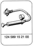
Special tools


A. Procedure

Shop-made, Model 124.036
only
Bracket for mounting retainer for plug from
coolant Pre-heater
a) Models 124.020/080 (engine 102.92), 124.021/041/081 (engine 102.96)
124.023/043/083 (engine 102.98)
1 Disconnect the ground cable from the
battery.
2 Remove the lower engine-compartment
insulation panels (Repair Manual 01-006).
3 Drain all coolant from engine (RA 20-010).

4 Unscrew the threaded plug (5) from the left side of the engine block.
Special tool 119 589 00 09 00.

5 Install O-ring on the coolant Pre-heater (1) , then thread heater into the engine block.
Tightening torque: 70 Nm.

6 Use cable straps (arrows) to attach the electrical lead from the coolant Pre-heater to the vacuum line.
Route lead well away from all potential sources of abrasion.

7 Use sheet-metal screws (14) to attach spring clamp (13) and cap (12) to the left-side firewall (see diagram). Use the socket which is already present in the firewall and drill a second hole with a 3 mm diameter.

Diagram
12 Cap
13 Spring clamp
14 Screw (B3.9 x 9.5)
15 Washer (A4.3)
8 Reconnect the battery ground cable.

9 Refill the engine cooling system
(RM 20-010).
10 Check the cooling system for leaks
(RM 20-017). Special tool 124 589 15 21 00.
11 Install lower engine compartment insulation panel (RM 01-006).
b) Model 124.034 (119.975 engine), 124.036 (119.974 engine)

1 Disconnect the ground cable from the battery.
2 Remove the lower engine-compartment insulation panels.
3 Drain all coolant from engine (RA 20-010).

4 Unscrew the threaded plug (b) from the left side of the engine block.
Special tool 119 589 00 09 00.
5 Place O-ring on the coolant Pre-heater and thread heater into the engine block.
Special tool 119 589 00 03 00.
Tightening torque: 70 Nm.

6 Route the electrical lead to the coolant Pre-heater toward the front, attaching it to the coolant pipe with cable straps (arrows).

7 Continue by attaching the electrical lead to the oil cooler line with clamp (01). Then run the wire beneath the line to the receiver/drier (AC) before running the wire upward at the left wheelhousing; attach with cable straps.
Route electrical leads so as to maintain the maximum possible distance between wiring and sources of heat and abrasion such as drive belts and the exhaust manifold.
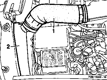
8 Remove the left-side air-intake hose (1). Extract the air-intake shroud (2) behind the left headlight upward and out.
9 Remove the left-side headlight.

10 Remove the shroud (3) behind the left-side headlight by unscrewing the four bolts (arrows). Remove the hood-release cable from the clip (4).
11 Pull the electrical wires for the headlights and their rubber grommets toward the rear to remove. Swivel the shroud (3) toward the front.

12 Route the electrical lead along the wiring harness at the left-side wheelhousing (below the headlight housing) and attach at the factory-installed cable straps (arrows).

13 Attach the spring clamp (13) and the cap (12) for the plug to the shop-made bracket (11).
11 Bracket (shop-made)
12 Cap
13 Clamp
14 Screw (B3, 9x9.5)
15 Washer (A4, 3)

14 Bolt the bracket (shop-made) with plastic nut for mounting the switchover valve to the left side off the firewall.
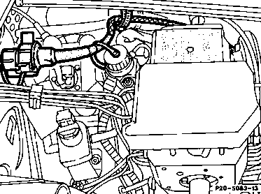
15 Install shroud (3), air-intake shroud (2), air-intake hose (1) and left headlight.
16 Reconnect the battery ground cable to the battery.
17 Refill system with coolant (RM 20-017).
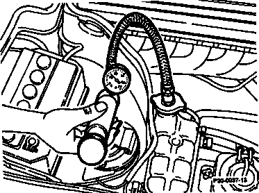
18 Check cooling system for leaks
(RM 20-017), Special tool 124 589 15 21 00.
19 Install lower engine-compartment encapsulation panel.
c) Model 124.120/180 (engine 601.91), 124.125/127/185 (engine 602.91),
124.13/190 (engine 603.91), 124.330 (603.913 engine)
1 Disconnect the ground cable from the battery.
2 Remove the lower engine-compartment encapsulation panel (RM 01-006).

3 Completely drain coolant from engine
(RM 20-010).
4 Unscrew the threaded plug (b) from the right side of the engine block.
Special tool 119 589 00 09 00.
Engine 601
12 Hex. bolt

Engine 602/603
12a Drain plugs
5 Fit the O-ring and screw the coolant Pre-heater unit into the engine block.
Tightening torque : 70 Nm.

6 Route the electrical lead for the coolant Pre-heater along the right side of the engine block and to the attachment point at the front.
Route lead well away from all potential sources of chafing and abrasion.
1 Engine block heater
2 O-ring
6 Clamp
7 Combination bolt with Allen fitting (M6x22)

7 Continue by using a clamp to attach the lead to the engine mount. Clamp the wire to the alternator bracket and then connect it to the main alternator harness with three cable straps (arrows). Run the wire to the right side member and attach it with three cable straps (arrows) using the holes provided at the factory.
8 Clamp
10 Combination hex. bolt (M8x45)


8 Drill two holes, dia. 3mm, in the right side member for attaching the spring clamp (13) and the cap (12) with two sheet-metal screws (14) (see diagram).
Coat the holes with zinc paint.
Mounting diagram
12 Cap
13 Spring clamp
14 Screw (B3, 9x9.5)
15 Washer (A4, 3)
9 Reconnect the ground cable to the battery.
10 Refill system with coolant (RM 20-010).
11 Check cooling system for leaks
(RM 20-017).
Special tool 124 589 15 21 00.
12 Install lower engine-compartment encapsulation panel (RM01-006).
d) Model 124.128/188 (engine 602.96), 124.133/193 (engine 603.96),
124.333/393 (engine 603.96)
1 Disconnect the ground cable from the
battery.
2 Remove the lower engine-compartment encapsulation panel (RM 01-006).
3 Completely drain coolant from engine
(RM 20-010).

4 Unscrew the threaded plug (b) from the right side of the engine block.
Special tool 119 589 00 09 00.
5 Fit the O-ring and screw the
coolant Pre-heater unit into the engine block.
Tightening torque: 70 Nm.

6 Use two hex. combination bolts and washers (M6x15) (3) to attach the heat shield (4) above the block heater (1).
7 Route the electrical lead for the block heater down the right side of the block and secure it in place.
Route lead well away from all potential sources of chafing and abrasion.
1 Engine block heater
2 O-ring
3 Hex. combination bolt and washer (M6x15)
4 Heat shield
5 Washer A8.4 (3 mm)
6 Clamp
7 Combination Allen bolt and washer (M6x22)

8 Continue by running the lead along the heater core return line (9) below the engine to the left side of the vehicle. Secure the lead with cable straps.
Right side of engine block

Lower right front of engine block

9 Run the lead to the left side of the firewall and attach it with cable straps (arrows).

10 Drill two holes, dia. 3 mm, in the left side of the firewall as attachment points for the spring clamp (13) and the cap (12) with two sheet-metal screws (14) (see diagram).
Mounting diagram
12 Cap
13 Spring clamp
14 Screw (BZ 4.2 x 16)
15 Washer (A4,3)
11 Reconnect the ground cable to the battery.
12 Refill the system with coolant (RM 20-010).
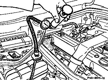
13 Check cooling system for leaks
(RM 20-017).
Special tool 124 589 15 21 00.
14 Install lower engine-compartment encapsulation panel (RM 01-006).
e) Models 124.007/026/027 (engine 103.94), 124.226 (engine 103.94)
124.030/050/090 (engine 103.98), 124.230/290 (engine 103.98)
124.008/028/029/088 (engine 104.942)
124.031/051/091 (engine 104.98), 124.061 (engine 104.98)
124.032/052/066 (engine 104.992)

1 Disconnect the ground cable from the battery.
2 Remove the lower engine-compartment encapsulation panel (RM 01-006).
3 Completely drain coolant from engine
(RM 20-010).
4 Unscrew the threaded plug (b) from the right side of the engine block.
Special tool 119 589 00 09 00.
5 Fit the O-ring and screw the coolant pre- heater unit into the engine block.
Tightening torque : 70 Nm.

6 Use two hex. bolts (M6x15) with washers to attach the heat shield (6) above the block heater (1).
7 Run the electrical lead from the coolant Pre-heater along the right side of the engine block and toward the front. Route the lead over the attachment point on the engine subframe and attach with clamps.
The attachment components must be mounted on the engine subframe in the following sequence:
7 Washer A8.4 (3 mm) between engine subframe and clamp
8 Clamp
9 Washer A8.4 (1.5 mm)
10 Hex. bolt (M8x40)
Route electrical leads so as to maintain the maximum possible distance between wiring and the exhaust manifold. Avoid installing near potential sources of abrasion.
Mouting on engine:
1 Engine block heater
2 O-ring
3 Clamp
4 Clamp (A6.4)
5 Hex. bolt (M6x15)
6 Heat shield
7 Washer A8.4 (3mm)
8 Clamp
9 Washer A8.4 (1.5mm)
10 Hex. bolt (M8x40)


8 Continue by using clamps to attach the lead to the engine block and to the alternator bracket, then connect it to the main alternator harness with three cable straps (arrows). Run the wire to the right side member.
Mouting on engine block and alternator bracket:
8 Clamp
9 Washer A8.4 (1.5 mm)
11 Hex. bolt (M8x20)
Ensure that the wire is routed well away from drive belts and pulleys.
9 Drill two holes, dia. 3 mm, and attach the spring clamp (13) and cap (12).
Mounting diagram:
12 Cap
13 Spring clamp
14 Screw (B3.9x9.5)
15 Washer (A 4.3)
Coat holes with zinc paint.
10 Reconnect the ground cable to the battery.
11 Refill the system with coolant (RM20-010).
12 Check cooling system for leaks (RM20-017).
Special tool 124 589 15 21 00.
13 Install lower engine-compartment encapsulation panel.
f) Model 124.019/040/079 with 111.940 engine (except vehicles with Tempomat)
Model 124.022/042/082 with 111.960 engine (except vehicles with Tempomat)
1 Disconnect the ground cable from the battery.
2 Remove lower engine-compartment encapsulation panel (Maintenance manual).
3 Completely drain coolant from engine
(RM 20-1142).
4 Remove the starter (RM 15-7100).

5 Unscrew the threaded plug (1) from the left side of the engine block,
Special tool 119 589 00 09 00.

6 Fit the O-ring and screw the coolant Pre-heater unit into the engine block.
Tightening torque : 70 Nm.

7 Route the electrical lead for the coolant pre- heater along the engine's wiring harness to the left side member and attach.
Route wire well away from potential sources of chafing and abrasion.
8 Use sheet-metal screws (14) to attach the spring clamp (13) and cap (12) to the left side member (see mounting diagram).
Use the factory-drilled hole in the side member and drill a second hole with a 3 mm dia.
Be certain to coat the sockets with zinc paint.
Mounting diagram
12 Cap 14 Screw (BZ 4.2x16)
13 Spring clamp 15 Washer (A4.3)

9 Install the wire clamp (000 995 80 44) behind the plug on the left side member.
10 Suspend the remaining electrical wire from the coolant Pre-heater in the wire clamp, coiling any excess in loops.
Ensure that the wire is routed well away from drive belts and pulleys.
11 Refill the system with coolant (RM 20-1142).
12 Check the cooling system for leaks
(RM 20-1010).
Special tool 124 589 15 21 00.
13 Install starter (RM-7100).
14 Install lower engine-compartment encapsulation panel (WHB).
15 Connect the battery ground cable.
B. Parts ordering note
Consult the parts documantation for a listing of the components required for installation:
Number | Description | Group/Option |
1 | Coolant Pre-heater kit | SA 12.228 |
Additional requirements according to model:
Model 124.034/036
Number | Description | Part no. |
1 | Collar clamp (dia. 8 mm) | 115 995 03 65 |
Models 124.020/125/127/130/180/190/330
Number | Description | Part no. |
1 | Clamp | 916016 006202 |
Models 124.128/133/188/193/333/393
Number | Description | Part no. |
1 | Heat shield | 602 200 00 94 |
Models 124.007/008/026/027/028/029/030/031/032/050/051/052/061/066/088/090/091/226/230/290
Number | Description | Part no. |
1 2 1 2 1 2 | Heat shield Clamp Washer B8 Washer B6 Hex. bolt M8x220 Hex. bolt M6x15 | 602 200 00 94 916016 006202 000137 08204 000137 006204 000933 008045 000933 006102 |
Models 124.019/022/040/042/079/082
Number | Description | Part no. |
1 | Cable clamp | 000 995 80 44 |
Referenced documents
- ar2000p1010ha
- ar2000p1010ha Inspect cooling system for leaks
- ar2000p1142ha
- ar2000p1142ha Drain/pour in coolant
- ra01001020006x 0006 - Removal and installation of the bottom engine compartment fairing Models 124, 201
- ra01006010006x 0006 - Removal and installation of noise capsule part at bottom of engine comp. Engines 601, 602 (except 602.98), 603
- ra01981020006x 0006 - Removal and installation of the engine compartment bottom panel Engine 102 KE in model 201
- ra01mr1020006x 0006 - Removal and installation of the engine bottom compartment panel Engine 102, multi-belt drive
- ra15001247100x 7100 - Removal and installation of the starter Engines; A. 102, 103, 104, 111, 601, 602, 603, 605, 606, B. 119.974/975 Model 124
- ra20001020010x 0010 - Draining, filling coolant Anti-freeze protection table Engine 102 (except 102.983/99), single-belt drive
- ra20001020017x 0017 - Checking the cooling system for leaks Engine 102 (except 102.983/99), single-belt drive
- ra20001030100x 0100 - Draining, pouring in coolant Anti-freeze protection table Engine 103
- ra20001030170x 0170 - Checking the cooling system for leaks Engine 103 (note deviations for off-road vehicles)
- ra20001040100x 0100 - Draining,pouring in coolant, anti-freeze protection table Engine 104
- ra20001040170x 0170 - Testing the cooling system for leaks Engine 104
- ra20001190100x 0100 - Draining and filling coolant, anti-freeze protection table Engine 119 in Models 124, 129, 140, and 210
- ra20001190170x 0170 - Leak test of the cooling system Engine 119 in Models 124, 129, 140, and 210
- ra20006010010x 0010 - Draining and filling coolant Antifreeze protection table Engines 601, 602 (except 602.98), 603
- ra20981020010x 0010 - Draining and adding coolant to the system Anti-freeze table Engine 102.983/99 KE in model 201
- ra20981020017x
- ra20981020017z 0017 - Testing the cooling system for leaks Engine 102.983/99 KE in model 201
- ra20mr1020010x 0010 - Draining and addition of coolant Anti-freeze protection table Engine 102, multi-belt drive
- ra20mr1020017x 0017 - Testing the cooling system for leaks Engine 102, multi-belt drive
- ra82001244730x 4730 - Removing and installing headlamp unit Model 124
- wh6190pkw0000x 6190 - Removal and installation of the bottom engine compartment paneling Models 124.0/2 to 6/93, 129 to 6/93, 140.0 to 6/93, 201.0
- wh9490pkw0000x 9490 - Removing and reinstalling bottom noise encapsulation panels Models 124.1/3 to 6/93, 126.1 (USA) from 1986, 140.34 to 6/93, 201.1