
Y26.40-0023-09
Middle Housing Removal |
1 | Reverse Idler Gear | 5 | Shim | |
2 | Needle Roller Bearing | 6 | Race | |
3 | Bush | 7 | Internal Puller | |
4 | Main Shaft Race | 8 | Counter Stay |

Y26.40-0024-09
1 | Reverse Idler Gear | 6 | Race | |
2 | Needle Roller Bearing | 9 | Pilot Bush | |
3 | Bush | 10 | Drift | |
4 | Main Shaft Race | 11 | Retaining Device | |
5 | Shim |

Y26.40-0025-09
11 | Retaining Device | 16 | 2nd and 3rd Pivot Bolt | |
12 | Counter Shaft | 17 | High Splitter Annular Spring | |
13 | Main Shaft | 18 | Synchronizer Cone | |
14 | D-Clamp | 19 | Synchronizer Ring | |
15 | 1st Pivot Bolt | 20 | Sliding Sleeve |

Y26.40-0026-09
21 | Input Shaft | 24 | Oil Pipe | |
22 | Idler Shaft | 25 | Splitter Fork | |
23 | Idler Shaft Retainer Plate | 26 | Guide Tube |

Y26.40-0033-09
27 | Front Housing | 30 | Taper Roller Bearing Outer Race (Main Shaft) | |
28 | Lock | 31 | Input Shaft Shim | |
29 | Taper Roller Bearing Outer Race (Counter Shaft) | 32 | Counter Shaft Shim |
| Remove | ||
1 | Remove the reverse idler gear (1) with needle roller bearing (2) and bush (3) from middle housing | ||
2 | Remove the main shaft race (4) along with shim (5) from middle housing using drift and hammer | ||
3 | Remove the race (6) of the counter shaft from middle housing using drift and hammer | ||
4 | Remove the pilot bush of the splitter from middle housing using internal puller (7) and counter stay (8) | Internal extractor | |
Counter stay | |||
5 | Remove the pilot bush of the range group from middle housing using internal puller (7) and counter stay (8) | Internal extractor | |
Counter stay | |||
| Install | ||
6 | Install pilot bush (9) of the range group to middle housing using drift | Drift | |
7 | Install pilot bush (9) of the splitter to middle housing using drift | Drift | |
8 | Install the race (6) of the counter shaft to middle housing using drift (10) and hammer | ||
9 | Install the shim (5) and race (4) of the main shaft to middle housing using drift (10) and hammer | ||
10 | Install the reverse idler gear (1) with needle roller bearing (2) and bush (3) to the middle housing | Lubricate the reverse idler gear with gearbox oil before installation. | |
11 | Install the retaining device (11) | Retaining device | |
12 | Install the counter shaft (12) and lock the retaining device (11) using D-clamp and crane | Retaining device | |
13 | Install the main (13) and counter shaft (12) along with shift fork and rails to middle housing and remove the D-clamp (14) with crane | While installing the main and counter shaft on the housing, pull the reverse gear on middle housing due to easy installing of main and counter shaft. | |
14 | Install and tighten the reverse and 1st pivot bolt (15) using sealant on both sides to middle housing | While installing pivot bolt, apply the thread lock sealant. | |
Loctite 243 | |||
Tighten the reverse and 1st pivot bolt | |||
15 | Install and tighten the 2nd and 3rd pivot bolt (16) on both sides to middle housing | While installing pivot bolt, apply the thread lock sealant | |
Loctite 243 | |||
16 | Remove the main and counter shaft from the clamping device | Clamping device | |
17 | Install the high splitter annular spring (17), synchronizer cone (18), synchronizer ring (19) to main shaft using screwdriver | ||
18 | Install the sliding sleeve (20) to splitter synchronizer hub | Long collar in the sliding sleeve has to face the output shaft. | |
19 | Install the input shaft (21) with low splitter synchronizer pack to main shaft | Apply silicon based grease. | |
20 | Install the reverse idler shaft (22) to the middle housing using mallet | ||
21 | Install reverse idler shaft retaining plate (23) | Tighten the reverse idler shaft retainer plate | |
22 | Install the oil pipe (24) to middle housing | ||
23 | Install the splitter fork (25) with wear pad to sliding sleeve | ||
24 | Insert the guide tube (26) to the oil pipe (24) for easy assembling to the front housing | Alignment punch | |
25 | Clean the sealing surfaces of the front and middle housing | Apply sealant on the sealing area of the middle housing. | |
Loctite 5203 sealant | |||
26 | Install front housing (27) to middle housing | Front housing to middle housing | |
27 | Install the lock (28) of the oil pipe to front housing using screwdriver and remove the guide tube from the oil pipe | ||
28 | Install taper roller bearing outer race (29) of the counter shaft | Apply synthetic grease. | |
29 | Install taper roller bearing outer race (30) of the main shaft | ||
30 | Install input shaft shim (31) and counter shaft shim (32) |
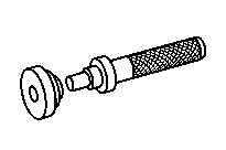


714 589 05 15 00
Drift
000 589 33 33 00
Counter stay
715 589 03 15 00
Alignment punch
000 589 26 33 00
Internal extractor


315 589 02 31 00
Clamping device
715 589 01 31 00
Retaining device