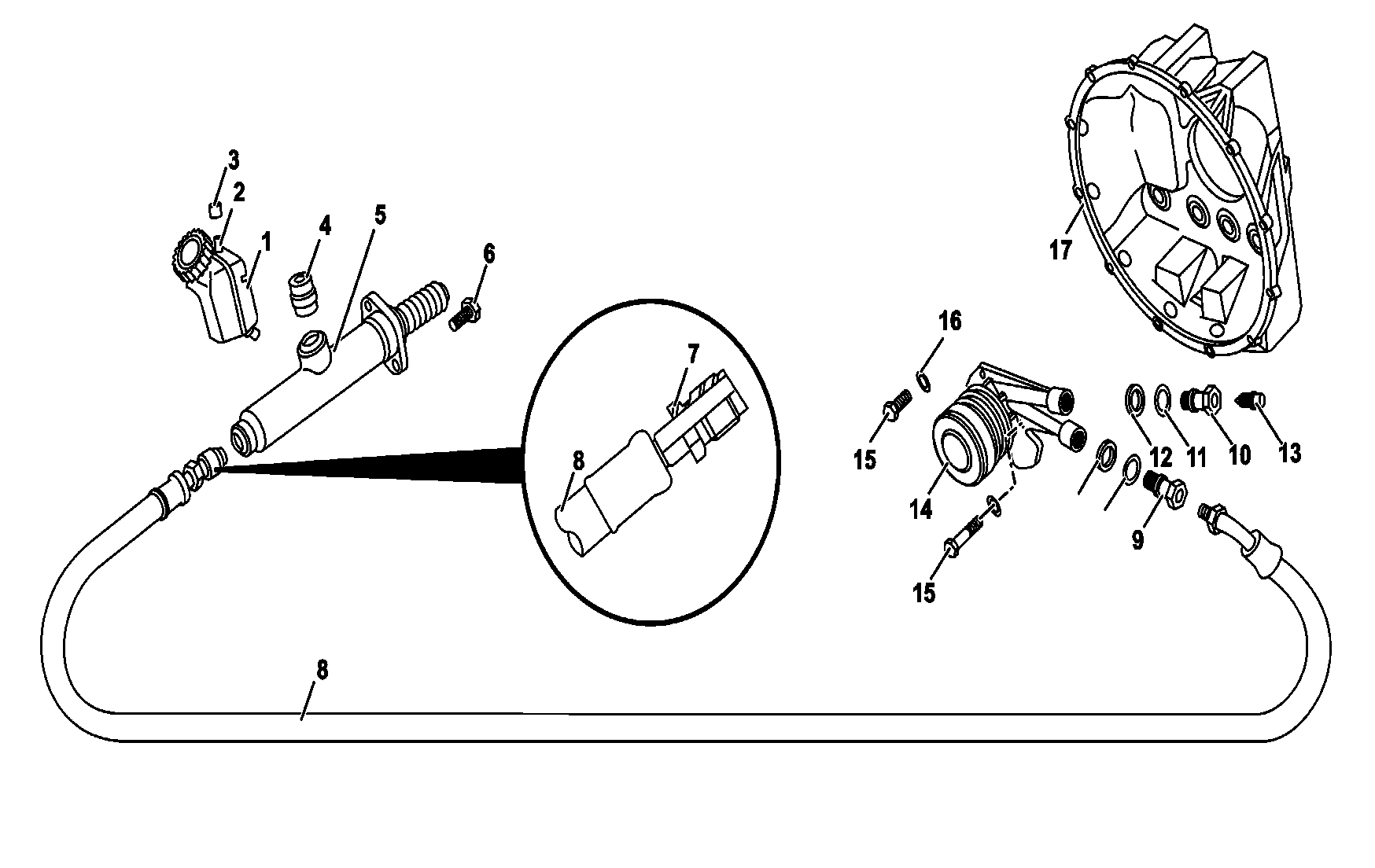
B25.20-0024-09
1 Hydraulic reservoir
2 Vent
3 Vent plug
4 Elastic connection ring
5 Master hydraulic cylinder
6 Cylinder set screw
7 Male cylinder connection nut
8 Hydraulic polyamide hose (PA 11)
9 Connection pipe (drive unit input)
10 Bleeding pipe
11 O-rings
12 Protection rings
13 Bleeder (with lid)
14 Drive unit
15 Fastening bolts
16 Washers
17 Gearbox
| Remove and install | ||
The hydraulic line described here is standard, may present small length differences and in the form of attachment of the pipes according with type of vehicle. | |||
The polyamide pipe is manufactured in accordance with strict quality standards. If provides great resistance and easy handling. However, it should not be excessively kinked nor rub sharp edges. | |||
1 | Unplug main switch | ||
2 | Open the front cover | ||
Danger! | Risk of poisoning by ingestion of brake fluid Risk of injury by contact of the skin and eyes with the brake fluid | Bleed off and store the brake fluid only in the original package. Wear protective clothing and goggles. | |
3 | Remove the hydraulic tank fluid (1) by suction. Use the bleeder to remove all hydraulic fluid from the piping | | |
Collect the brake fluid in a suitable container and dispose of it in an environmentally friendly way. The brake fluid, once removed, should never be reused. | |||
4 | Cut the plastic clip attaching the piping (8) on the bundle on the front part | Install: Fit the piping (8) in the bundle along with the other pipes throughout its length. Install new clips to attach the bundle formed by the pipes. | |
5 | Loosen the connection (7) on the master cylinder (5), and release the polyamide pipe (8) on the front side | ||
Danger! | Risk of injury trapping and crushing when tilting the cabin | While tipping the cabin back and forth, do not enter the tipping area and take preventive measures to prevent unauthorized people from entering the area. Always tilt the cabin up to its final position and lock it with the safety device. | |
6 | Tilt the cabin | ||
7 | Loosen the connection polyamide pipe (8) connection from the lower end on the input connection (9) to the drive unit | Rotate the male nut (8) on the connection pipe (9). | |
8 | Cut the plastic clip attaching the pipe (8) on the bundle on the central part | Install: Accommodate the pipe and install new plastic clips. | |
9 | Remove the pipe (8) carefully without kinking it | Install: The piping (8) should be previously attached to the master cylinder (5) and to the connection pipe (9), so that it is not forced nor kinked. | |
10 | Remove the bleeder (13), the connection pipe (9), the bleeding pipe (10), the protection rings (12) and O-rings (11) | Install: Fit new O-rings and protection rings. | |
| Clean | ||
11 | Clean all components with alcohol, including the piping | The hydraulic components should not be cleaned with gasoline, kerosene or diesel oil. Petroleum-derived products damage rubber components. | |
Apply dry, clean compressed air into the pipes. Should they remain in storage, their ends should be plugged with suitable plastic plugs. | |||
| Check | ||
12 | Check the conditions of the piping (8) and all sealing components | Replace: Cut or deformed piping, if it presents bad or stripped connections. All plastic attachment clips. O-rings and protection rings (11) and (12) of the connection pipe (9) and bleeding pipe (10). Damaged filter or reservoir. If necessary, replace the bleeder (13) with the protection lid. | |
13 | Install in reverse order | ||
14 | Refill the hydraulic tank with new brake fluid | Use specified brake fluid. | |
15 | Bleed the hydraulic system | ||
16 | Check for leaks | ||
17 | Check the perfect operation of the clutch |
Produtos para reparos
Número | Denominação | Número de pedido |
BR00.45-B-1011-06A | Brake fluid as per DBL 7760.30 (DOT 4) | - |
Referenced documents
- ar2520b0070b Bleed clutch operating system
- ar6080b0010a Tilt cab to repair position, tilt back
- as4250b000101a Risk of poisoning from swallowing brake fluid. Risk of injury from skin and eye contact with brake fluid
- as6080b000101a Risk of injury caused by body parts being pinched or crushed as cab is tilted