AR09.41-B-8620D | Remove/install charge air ducts | 12.02.16 |
Cumbustion engine 457 with Vehicle 696.080
Cumbustion engine 457.931 with Vehicle 696.090, 696.365, 696.367, 696.369
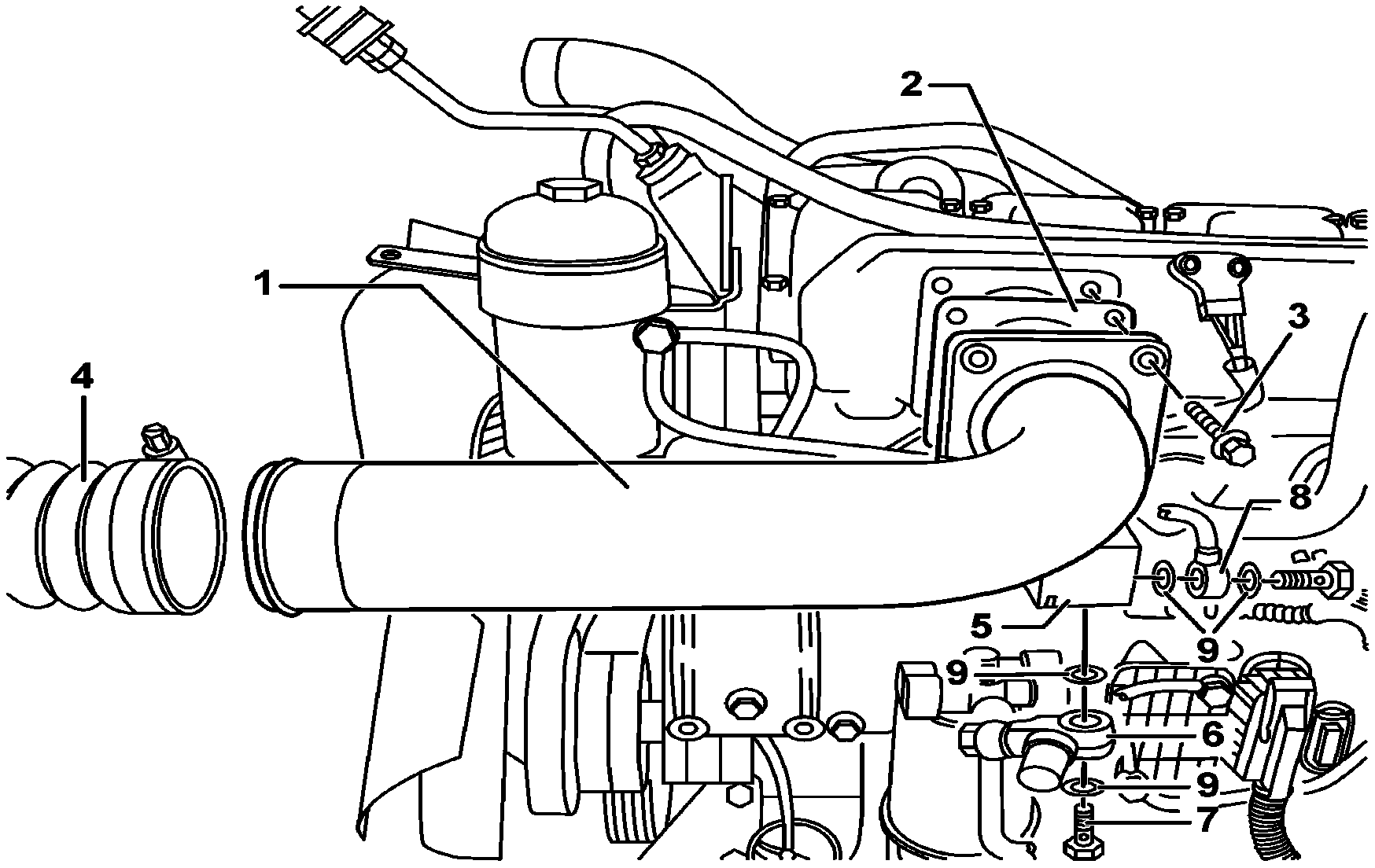
B09.41-0022-11
1 After-cooler air distribution manifold
2 Joint
3 Bolts
4 Hose (black)
5 Connection/support
6 Hand primer pump
7 Hollow screw
8 Fuel tubes
9 Sealing rings
| Remove and install | ||
1 | Disconnect the negative cable from the battery terminal. | ||
Danger! | Risk of injury due to being caught or smashed when opening and shutting the engine hood cover | During the hood cover tilting, keep always the area free of people and objects. | |
2 | Tilt the engine hood. | ||
Danger! | Risk of explosion by inflammation, risk of poisoning by inhalation and fuel ingestion, as well as risk of injury by contact of fuel to the skin and eyes | It is forbidden to smoke, set fire, sparks or open flame. Only store fuel in appropriate and respectively identified containers. When handling fuel use appropriate protective clothing and equipment. | |
3 | Disconnect the fuel tubes (8) in the connection (5) at the manifold (1). | Collect the fuel. Install: Replace the sealing rings (9). | |
| |||
4 | Remove the hollow bolt (7) and disconnect the hand primer pump (6) from the connection (5) in the manifold (1). | Collect the fuel. Install: Replace the sealing rings (9). | |
| |||
5 | Remove the hose (4) from the manifold (1). | Install: Do not reverse the hoses position. The black hose (4) must be assembled in the connection between the after-cooler and the manifold (1) and the red hose between the air after-cooler and the turbocharger. | |
Indications for the assemblage of after-cooler air hoses. | |||
| |||
6 | Unfasten the bolts (3), remove the manifold (1) and the joint (2). | In order to avoid the penetration of dirt, protect the charge air manifold and after-cooler air mouths. Install: Replace the joint (2). | |
| |||
7 | Install in reverse order. | ||
8 | Bleed the fuel system. | Act on the handle of the hand primer pump until strong resistance is observed. | |
Danger! | Risk of accident due to the involuntary movement when the engine is operating. Risk of injury caused by smashing and burns due to contact during the start-up process or with the operating engine | Make sure that the vehicle will not accidentally move. Wear work clothes well closed and tight. Do not touch the heated or moving parts. | |
9 | Operate the engine and check the tightness of the fuel system. | Do not run the starter continuously for more than 30 seconds. Should the engine not start within this interval, wait for approximately 1 minute to crank it again. | |
10 | Stop the engine. |
Fuel pump
Número | Denominação | Engine 457.9 | |||
BA47.20-B-1003-01B | Manual supply pump bolt to air intake manifold support | Nm | 45 | ||
BA47.20-B-1004-01B | Fuel tubing hollow screw to manual supply pump | Nm | 50 | ||
Charge air pipe/charge air cooling
Referenced documents
- ah0941b000101a Notes on the installation of charge air hoses downstream of the charge air cooler
- ap4700b172001d Bleed fuel system
- ar8840b1000b Opening engine hood, moving to upright position and closing
- as0000b000501a Risk of accident from vehicle starting off by itself when engine running. Risk of injury (bruises and burns) resulting from working on the engine while it is being started or when it is running.
- as4700b000101a Risk of explosion caused by fuel igniting, risk of poisoning caused by inhaling and swallowing fuel as well as risk of injury to eyes and skin caused by contactwith fuel.
- as8840b000101a Risk of injury caused by pinching and crushing when opening and closing engine hood