
W07.16-1181-09
1 | Fuel system high pressure pump | 3 | Drive plate (only for vehicles with steered leading axle or trailing axle) | 7 | Puller | ||
2 | Locating tool | 4 | Nut | 8 | Dowel pin | ||
2.1 | Adaptation | 5 | Positioning disc | 9 | Screw/bolt | ||
2.2 | Adaptation | 6 | Drive gear | Pfeil | Pin |
| Remove | ||
1 | Remove fuel system high pressure pump (1) | ||
2 | Clamp locating tool (2) into the vise and attach adaptations (2.1, 2.2) | Adaptation | |
Locating tool | |||
3 | Attach fuel system high pressure pump (1) to the locating tool (2) | ||
4 | Remove drive plate (3) | Only for vehicles with steered leading axle or trailing axle. | |
5 | Slacken nut (4) | ||
6 | Loosen drive gear (6) with puller (7) from the drive shaft | Puller | |
7 | Unscrew nut (4) | ||
8 | Remove drive gear (6) from the fuel system high pressure pump | ||
9 | Check drive gear (6) for damage; replace if necessary | If drive gear (6) is replaced because of damage, the gear for the gearwheel drive must also be checked for damage. | |
10 | Remove position disc (5) from drive gear (6) | Only for vehicles with steered leading axle or trailing axle or if the drive gear (6) is replaced. | |
11 | Check dowel pin (8) for wear and damage; replace if necessary | ||
| Install | ||
12 | Attach position disc (5) on drive gear (6) | Only for vehicles with steered leading axle or trailing axle or if the drive gear (6) is replaced. | |
Ensure that the lugs (arrow) on the positioning disc (5) engage in drive gear (6). | |||
Screw/bolt, positioning disk/driver to fuel system high-pressure pump drive wheel | |||
13 | Attach drive gear (6) to the fuel system high pressure pump (1) | The cone of the drive shaft and the tapered seat of the drive gear (6) must be free of grease. | |
14 | Tighten nut (4) | Nut, drive wheel to fuel system high-pressure pump | |
15 | Install drive plate (3) | Only for vehicles with steered leading axle or trailing axle. | |
Screw/bolt, positioning disk/driver to fuel system high-pressure pump drive wheel | |||
16 | Remove fuel system high pressure pump (1) from the locating tool (2) | ||
17 | Install fuel system high pressure pump (1) |
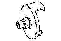


936 589 05 33 00
Puller
470 589 08 40 00
Locating tool
936 589 00 31 00
Adaptation
Referenced documents
- ar0716w1005md Remove/install high-pressure fuel pump