
1 | Bracket |
2 | Electrical connector |
3 | Rail |
B622 | Rail pressure sensor |
W07.04-1098-11
Danger | Risk of explosion caused by fuel igniting. Risk of injury to skin and eyes caused by fuel spraying out at high pressure | Keep all ignition sources out of hazard area. | |
Danger | Risk of explosion caused by fuel igniting, risk of poisoning caused by inhaling and swallowing fuel as well as risk of injury to eyes and skin caused by contactwith fuel. | No fires, sparks, open flames or smoking. Pour fuels into suitable and appropriately marked containers only. | |
Warning | Risk of accident from vehicle starting off by itself when engine running. Risk of injury (bruises and burns) resulting from working on the engine while it is being started or when it is running. | Secure vehicle to prevent it from starting off by itself. Wear closed and snug-fitting work clothes. Do not touch hot or rotating parts. | |
Warning | Risk of injury caused by body parts being pinched or crushed as cab is tilted | Ensure that no one is within the tilting range of the cab as it is being tilted. Always tilt the cab all the way to the end position and secure it with the safety strut. | |
Topical note | Notes on tilting the cab | ||
Topical note | Notes on avoiding damage through contamination and foreign objects | ||
Notes on safety-relevant components | |||
| Remove/install | ||
1 | Tilt cab. | Installation: Only tilt back cab after the leak test. | |
2 | Remove noise encapsulation. | Installation: Only install soundproofing after the leak test. | |
3 | Remove bracket (1). | If present. | |
4 | Clean engine in the area of the rail pressure sensor (B622). | ||
5 | Disconnect electrical connection (2). | ||
6 | Remove rail pressure sensor (B622) from the rail (3). | Counterhold rail (3) at front on flange with an open end wrench. | |
Rail pressure sensor at rail | |||
Torque wrench | |||
Socket wrench bit | |||
7 | Install in the reverse order | ||
| Check | ||
8 | Perform engine test run. | Allow the engine to run at a higher engine speed. | |
If engine fails to start or only runs for a brief period, | |||
| |||
fill the fuel low-pressure circuit. | |||
9 | Check area of the rail pressure sensor (B622) for leak tightness. | Visual inspection. | |
10 | Connect diagnostic system, start XENTRY and perform quick test. | ||
11 | Check the engine management for proper operation. | ||
12 | End XENTRY and remove the diagnostic system. |

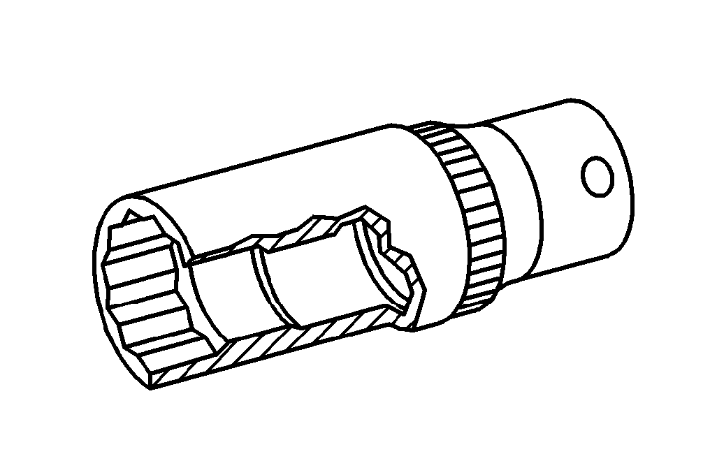
001 589 67 21 00
Torque wrench
001 589 65 09 00
Socket wrench bit
Referenced documents
- ah0000n500001h Notes on avoiding damage through contamination and foreign objects
- ah0000z001901a Notes on safety-relevant components
- ah6080n000301a Notes on tilting the cab
- ar0708w100001a Check engine management for proper operation
- ar0716w1007md Fill fuel low-pressure circuit on engine
- as0000z000501a Risk of accident from vehicle starting off by itself when engine running. Risk of injury (bruises and burns) resulting from working on the engine while it is being started or when it is running.
- as0716z000101b Risk of explosion caused by fuel igniting. Risk of injury to skin and eyes caused by fuel spraying out at high pressure
- as4700z000101a Risk of explosion caused by fuel igniting, risk of poisoning caused by inhaling and swallowing fuel as well as risk of injury to eyes and skin caused by contactwith fuel.
- as6080z000101a Risk of injury caused by body parts being pinched or crushed as cab is tilted