
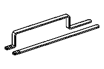

651 589 02 63 00
Assembly tool
651 589 00 40 00
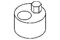
Counterholder
651 589 08 40 00
Counterholder
651 589 09 40 00
Holddown device
Use to turn the engine counterholder 651 589 00 40 00 or counterholder 651 589 08 40 00.

1 | Place respective counterholder on the screw/bolts for the belt pulley. |
2 | Turn engine with counterholder () in direction of engine rotation and set to ignition TDC (Top Dead Center). |
The 0° CKA marking on the belt pulley (1) must align with the stay (2) on the major assembly carrier. |
S01.10-4602-01

3 | Pull retaining pin (3.1) out from assembly tool (3). |
4 | Position engine on crankshaft with counterholder to 30° CKA after ignition TDC. |
The 30° CKA marking on the belt pulley must align with the stay (2) on the major assembly carrier. |
S05.10-4517-04
5 |
Move both halves of assembly tool (3) onto milled surfaces of balance shafts (4). |
6 |
Turn engine on crankshaft with counterholder against direction of engine rotation and set to ignition TDC; guide both halves of assembly tool (3) together and secure with retaining pin (3.1). |
The 0° CKA marking on the belt pulley (1) must align with the stay (2) on the major assembly carrier. |

7 | Mark assignment of the camshaft bearing cap (10). |
8 | Remove screw/bolts (9) and remove camshaft bearing cap (10) from the camshaft (7). |
Installation: Observe assignment of camshafts bearing caps (10) relative to one another. |
9 | Install hold-down tool (8) free of tension on camshafts (7) and tighten. |
D05.10-1181-06