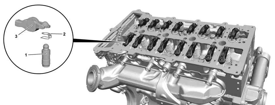
P05.00-A001-08
1 | Valve clearance compensating element | 2 | Clamp | 3 | Roller-type cam follower |
Caution | Risk of injury caused by scraping or cutting body parts on sharp vehicle parts | Always wear protective gloves when working on or near sharp and non-deburred vehicle parts. | |
Caution | Risk of injury to skin and eyes due to handling of engine oil. Risk of poisoning caused by swallowing engine oil | Wear protective gloves, protective clothing and safety glasses. | |
Topical note | Notes on avoiding damage through contamination and foreign objects | ||
| Remove/install | ||
1 | Remove camshaft housing with camshafts. | ||
2 | Mark roller-type rocker arms (3) together with valve clearance compensating elements (1) in relation to cylinder head. | If reusing roller-type rocker arms (3) and valve clearance compensating elements (1). | |
| |||
3 | Remove roller-type rocker arms (3) together with valve clearance compensating elements (1). | ||
| Specified engine oils (service) - Overview | ||
Installation: Wet roller-type rocker arms (3) and valve clearance compensating elements (1) with engine oil. | |||
4 | Remove clamps (2) by hand and remove valve clearance compensating elements (1) from roller-type rocker arms (3). | ||
| Check | ||
5 | Check compensating elements (1) for proper operation. | | |
It should not be possible to press the valve clearance compensating elements (1) together with normal force of the hand and they should move together only very slowly when great force is applied. | |||
If several valve clearance compensating elements (1) are defective: | |||
| |||
Check forced oil supply of cylinder head. | |||
Check oil pressure | |||
6 | Install in the reverse order. |
Referenced documents
- ah0000p500001a Notes on avoiding damage through contamination and foreign objects
- ar0520p6997mff Remove/install camshaft housing with camshafts
- ar1800p1250mff Check oil pressure
- as0000z001701a Risk of injury caused by scraping or cutting body parts on sharp vehicle parts
- as1800z000101a Risk of injury to skin and eyes due to handling of engine oil. Risk of poisoning caused by swallowing engine oil
- bb0040p022302a Specified engine oils for Cars, Vans (service) - Overview