Model | 207.4 |
with code 3U1 (Headunit europe/CIS-states/Monoglei) | |
with code 505 (Radio 20 NTG5, not navigation-enabled) | |
except code 512 (COMAND APS with DVD changer) | |
except code 527 (COMAND APS with single DVD drive (with navigation)) | |
except code P44 (Parking package) | |
Model | 207.4 |
with code 3U1 (Headunit europe/CIS-states/Monoglei) | |
with code 522 (Audio 20 CD including preinstallation for Garmin® MAP PILOT) | |
except code 512 (COMAND APS with DVD changer) | |
except code 527 (COMAND APS with single DVD drive (with navigation)) | |
except code P44 (Parking package) | |
Model | 207.4 |
with code 3U1 (Headunit europe/CIS-states/Monoglei) | |
with code 531 (COMAND APS) | |
except code 512 (COMAND APS with DVD changer) | |
except code 527 (COMAND APS with single DVD drive (with navigation)) | |
except code P44 (Parking package) |

Connection scheme |
1 | Backup camera wiring harness |
1.1 | White 12-pin plug |
1.3 | White 4-pin connector |
1.4 | Black 2-pin coupling |
1.5 | Green fuse holder |
2 | Adapter wiring harness |
2.1 | White 12-pin connector |
2.3 | White 12-pin connector |
3 | White 12-pin plug |
A2 | Radio |
A40/3 | COMAND control unit |
B84/3 | Backup camera |
N10/2 | Rear SAM control unit with fuse and relay module |
W7/7 | Right spare wheel well ground point |
X30/30 | Vehicle floor chassis CAN voltage distributor electrical connector |
X169 | Backup camera electrical connector |
br | Brown line |
ge | Yellow line |
ge/ws | Yellow/white line |
rt/bl | Red/blue line |
sw | Black line |
P54.65-5668-05

Routing diagram |
1 | Backup camera wiring harness |
2 | Adapter wiring harness |
A2 | Radio |
A40/3 | COMAND control unit |
B84/3 | Backup camera |
N10/2 | Rear SAM control unit with fuse and relay module |
W7/7 | Right spare wheel well ground point |
X30/30 | Vehicle floor chassis CAN voltage distributor electrical connector |
X169 | Backup camera electrical connector |
br | Brown line |
ge | Yellow line |
ge/ws | Yellow/white line |
rt/bl | Red/blue line |
sw | Black line |
P54.65-5669-05

1 | Remove vehicle's wiring harness (5). |
P54.65-5081-11

2 | Clip reversing camera (B84/3) into specified cutout in trunk lid. |
P54.65-5082-11
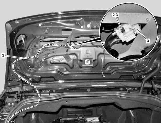
3 | Install adapter wiring harness (2). |
Use a pull-through device. |
4 | Connect white 12-pin plug (3) to white 12-pin connector (2.3). |
5 | Slip foam material over white, 12-pin plug (3) and white 12-pin connector (2.3). |
6 | Fix adapter wiring harness (2) in place using cable ties. |
P54.65-5670-06

7 | Connect white, 12-pin plug (1.1) for reversing camera wiring harness (1) to white, 12-pin connector (2.1) of adapter wiring harness. |
This makes the electrical connection for the reversing camera (X169). |
8 | Pull foam material over the reversing camera electrical connector (X169). |
9 | Route red/blue line (RD/BU) and brown line (BN) along existing lines to the rear SAM control unit with fuse and relay module (N102) and fix in place with cable ties. |
10 | Route black line (BK), twisted yellow line (YE) and yellow/white line (YE/WH) along existing lines into vehicle interior and fix in place using cable ties. |
Use a pull-through device. |
P54.65-5671-12

11 | Detach green fuse holder (1.5) from rear SAM control unit with fuse and relay module (N10/2). |
12 | Install red/blue line (RD/BU) into contact cavity 4 of green fuse holder (1.5). |
Contact cavity 4 of the green fuse holder (1.5) is labeled. |
13 | Attach green fuse holder (1.5) to rear SAM control unit with fuse and relay module (N10/2). |
The slot on the rear SAM control unit with fuse and relay module (N10/2) is marked green. |
14 | Insert a 7.5 A fuse into slot 4 of the green fuse holder (1.5). |
15 | Tie back excess length of the red/blue line (RD/BU) and fix in place using cable ties. |
16 | Route brown line (BN) under rear SAM control unit with fuse and relay module (N10/2) to right spare wheel well ground point (W77) and fix in place using cable ties. |
17 | Connect ground point on right spare wheel well (W7/7) to brown line (BN). |
P54.65-5673-12

18 | Route black line (BK), twisted yellow line (YE) and yellow/white line (YE/WH) along existing lines into line ducts in driver footwell and fix in place using cable ties. |
19 | Route twisted yellow line (YE) and yellow/white line (YE/WH) along existing lines and in cable ducts into driver footwell and fix in place using cable ties. |
P54.65-5086-11

20 | Connect twisted yellow line (YE) and yellow/white line (YE/WH) to vehicle floor chassis CAN potential distributor electrical connector (X30/30). |
21 | Route black line (BK) along ventilation duct to radio (A2) or COMAND controller unit (A40/3) and fix in place using felt tape. |
The black line (BK) is connected later on to the radio (A2) or the COMAND controller unit (A40/3). |
P54.65-5667-12