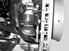


D46.20-1102-01
D46.20-1107-01
D46.20-1106-01
1 Brake disk
2 Nut
3 Tie rod end
4 Heat shield
8 Retaining clamp
9 Pressure line
10 Nut
5 Screw
6 Universal joint
7 Screw


D46.20-1103-01
D46.20-1105-01
D46.20-1104-01
11 Nut
12 Pressure line
13 Return flow pipe
17 Bolts
18 Bolts
14 Steering
15 Screw
16 Spring clamp plates
| Remove/install | ||
Danger! | Risk of death caused by vehicle slipping or toppling off of the lifting platform. | Align vehicle between columns of vehicle lift and position four support plates at vehicle lift support points specified by vehicle manufacturer. | |
1 | Suction off steering oil | | |
Hand pump | |||
2 | Lift/jack up vehicle | ||
3 | Remove front wheels | ||
4 | Unscrew nut (2) at tie rod end (3) | One each on left and right side of steering knuckle. | |
| |||
5 | Detach tie rod end (3) at left front and right front on steering knuckle using puller | Puller | |
6 | Turn steering (14) to right stop | ||
7 | Remove bolt (7) and loosen universal joint (6) on steering (14) | | |
8 | Remove nuts (10, 11) and loosen retaining clamps (8) at pressure line (9) | ||
9 | Remove bolt (15) and detach pressure line (12) and return line (13) from steering (14) | Seal line bores on steering (14), pressure line (12) and return line (13) with stop plugs. This prevents dirt from entering. Replace seals on pressure line (12) and return line (13). This prevents leaks. | |
| |||
| |||
Set of stop plugs | |||
10 | Remove left tie rod end (3) | Mark installation position and loosen jam nut just enough that the tie rod end (3) can be screwed out. | |
Installation: Secure tie rod end (3) with locknut at marked position. | |||
| |||
11 | Remove bolts (17) and remove left and right spring clamp plates (16) | Loosen bolts (17) uniformly in stages. Otherwise the spring clamp plates (16) will be pressed downwards approx. 10 mm when loosened. This can cause damage to the threads. | |
Installation: Pay attention to different lengths of bolts. | |||
| |||
12 | Remove bolts (18) and steering (14) | Carefully remove steering (14). Damage to the housing can result in leakage and malfunctions. | |
Installation: During installation, the universal joint (6) must first be inserted and then the bolts (18) fitted. | |||
| |||
13 | Install in the reverse order | ||
14 | Bleed steering (14) | ||
15 | Perform wheel alignment check |
Front axle steel suspension
Number | Designation | Model | Model | |||
BA32.20-N-1001-01A | Bolt, lower spring clamp plate to front axle beam | M121.5 | Stage 1 | Nm | 106 | 106 |
Stage 2 | ° | 90 | 90 | |||
M8 | Nm | 29 | 29 | |||
M10 | Nm | - | - | |||
Steering wheel, jacket tube, steering shaft
Number | Designation | Model | Model | ||
BA46.10-N-1003-05C | Universal joint to steering gear shaft | Nm | 28 | 28 | |
Steering gear
Number | Designation | Model | Model | ||
BA46.20-N-1001-01C | High-pressure expansion hose to steering gear | Nm | 18 | 18 | |
BA46.20-N-1002-01C | Return flow line to steering gear | Nm | 18 | 18 | |
BA46.20-N-1003-01C | Bolt, steering to front axle | Stage 1 | Nm | 25 | 25 |
Stage 2 | Nm | 80 | 80 | ||
Stage 3 | ° | 90 | 90 | ||
Steering linkage
Number | Designation | Model | Model | |||
BA46.40-N-1001-06D | Nut on ball head | M141.5 | Stage 1 | Nm | 50 | 50 |
Stage 2 | ° | 60 | 60 | |||
M161.5 | Nm | - | - | |||
BA46.40-N-1003-06D | Lock nut at ball head | Nm | 65 | 65 | ||
Steering
Number | Designation | Model | Model | ||
BF46.00-N-1001-01A | Steering gear oil | Filling capacity | Liters | 1.0 | 1.0 |
Specifications for Operating Fluids | Sheet | ||||



210 589 00 71 00
Puller
Hand pump
Set of stop plugs
129 589 00 91 00
221 589 05 33 00
Henviste dokumenter
- ar0060d1000h
- ar4010d1100h
- ar4020d0200h
- ar4630s0010s
- as0000z001001a Livsfare, hvis køretøjet glider ned fra eller tipper på liften.