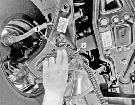
Shown on model 907, right side of vehicle |
1 | Transverse control arm |
3 | Measuring sensor |
D40.20-0056-11
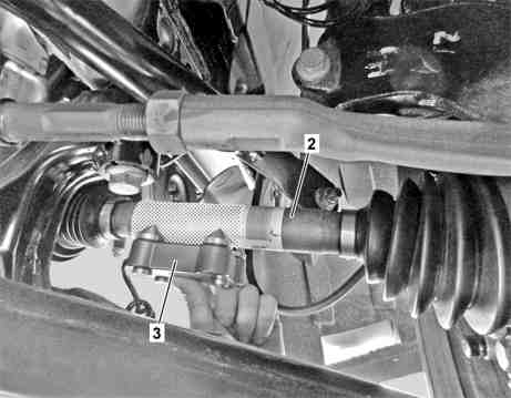
Shown on model 910, right side of vehicle |
2 | Front axle shaft |
3 | Measuring sensor |
D40.20-0055-11

Example illustration of vehicle model designation selection |
6 | Menu item |
7 | Inclination meter |
S40.20-4518-10
| Check | ||
1 | Check preconditions for wheel alignment. | ||
Position vehicle for measurement on suitable measuring station, e.g. work pit or 4-post vehicle lift. | |||
| Clean | ||
2.1 | Clean measuring points on left and right front transverse control arm (1). | Model 907 | |
2.2 | Clean measuring points on left and right front axle shaft (2). | Model 910 | |
If necessary, | |||
| |||
remove any adhesive labels. | |||
| Measure | ||
3 | Select menu item (6) in inclinometer (7). | ||
| 000 588 05 19 00 Vehicle level inclinometer | ||
Select corresponding vehicle model designation. Note operator's manual for inclinometer (7). | |||
4.1 | Mount measuring sensor (3) onto left front axle shaft (2) and save measured value. | Model 910 | |
| |||
4.2 | Mount measuring sensor (3) onto left transverse control arm (1) and save measured value. | Model 907 | |
| |||
5.1 | Mount measuring sensor (3) onto right front axle shaft (2) and save measured value. | Model 910 | |
| |||
5.2 | Mount measuring sensor (3) onto right transverse control arm (1) and save measured value. | Model 907 | |
| |||
6 | Calculate mean value and note down. | The mean value is required to assign the affected specified values for the toe-out angle as well as toe, camber, caster and steering axis inclination. |