AR32.22-T-7000B | Checking and adjusting vehicle level | 15.1.10 |
MODEL 613.355 /455 /485 with FRONT AXLE 739.234 with REAR AXLE 745.996
MODEL 613.358 /388 with FRONT AXLE 739.234 with REAR AXLE 745.997
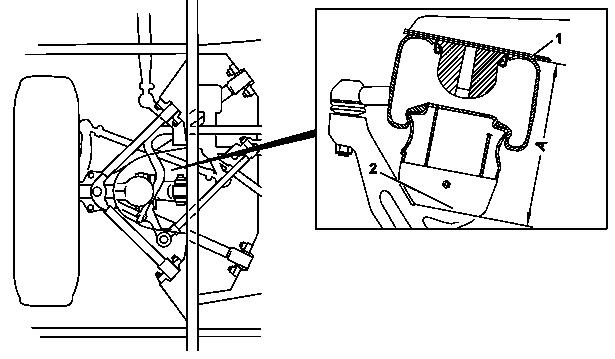
T32.22-0007-05
Shown on front axle
1 Lower edge of air suspension bellows mounting plate
2 Lower edge of rotary piston

T32.22-0009-06
Shown on rear axle
3 Lower edge of air suspension bellows mounting plate
4 Lower edge of rotary piston
5 Level control valve operating lever
6 Linkage rod
7 Rear axle housing
Modification notes
10.1.04 | Adjustment dimension for front axle suspension level modified. | Only model 613.355/358/388/455/485 | |
Adjustment dimension of rear axle suspension level | Only model 613.355/358/388/455/485 |
| Checking | ||
Danger! | Danger to life from lowering vehicle when working between wheels and body. Risk of injury by trapping or crushing when working on air suspension system. | Do not work between wheel and wheel well or in wheel box. Only carry out check and adjustment operations from underneath the vehicle. Secure areas with moving vehicle parts against unauthorized access. | |
| The suspension level is checked and adjusted with unloaded vehicle. The wheels must be in the straight-ahead position. Ensure an adequate compressed-air supply for the entire duration of the adjustment procedure. Setting the suspension level must always be carried out on both axles, starting with the front axle. | ||
1 | Put level control system in normal drive mode | See Operator's Manual | |
2 | Measure the suspension level of the front axle | The suspension level is the dimension between the lower edge of the air suspension bellows mounting plate (1) and the lower edge of the rotary piston (2) (dimension A). | |
Vernier caliper | |||
3 | Adjust the front axle suspension level | ||
4 | Measure the suspension level of the rear axle | The suspension level is the dimension between the lower edge of the air suspension bellows mounting plate (3) and the lower edge of the rotary piston (4) (dimension B). | |
Vernier caliper | |||
5 | Adjust the rear axle suspension level | ||
6 | Recheck the suspension level of the front and rear axles | Repeat the adjustment if necessary. |
Test data for air suspension
Henviste dokumenter
- ar3222t700001b
- as3222z000101a Livsfare på grund af sænkning af køretøjet ved arbejde mellem hjul og opbygning.Fare for personskade på grund af fastklemning eller knusning ved arbejde på luftaffjedringen.