
715 589 00 63 00
Assembly tool

Remove
1 | Place a steel bushing as a shim in the inner side of the transmission front part. |
The steel bushing must have approximately the same diameter that the bearing's snap ring to prevent that during the drive shaft's removal, the snap ring breaks the front part of the transmission. |
B26.50-0099-01

2 | Put the front part of the housing (1) with the steel bushing supported on the press base and push the drive shaft (2) until you remove it from its lodging. |
B26.50-0100-01
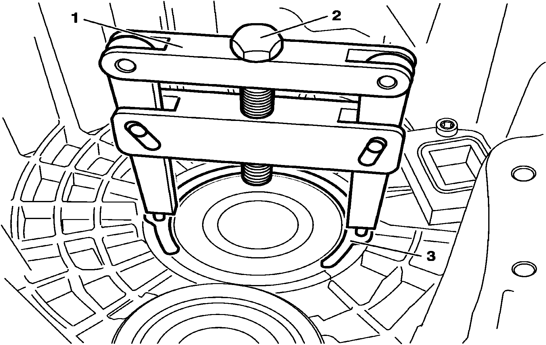
3 | Put the assemblage device in the snap ring orifices (3). |
Possibly one of the snap ring orifices (3) can be exactly above one of the transmission's back part oil holes. Consequently, one must pay attention not to permit that the claws of the assembly device (1) entangle in the oil hole. |
4 | Turn the hexagonal part (2) of the assemblage device (1) until the snap ring is compressed up to a point in which it is possible to remove-it from its fitting place at the transmission's front part. |
5 | Relief the assemblage device (1) and remove the snap ring (3). |
6 | Remove under pressure the radial bearing. |
W26.50-1020-11

Install
7 | Heat the transmission front housing, in the region of the radial ball bearing's coupling, up to approximately 80 ºC. |
8 | Install the radial ball bearing (1) in its lodging, by applying soft blows until it touches the housing stopper. |
Use, compulsorily, a new radial ball bearing. |
B26.50-0095-01
9 | Put a new snap ring (3) in the assemblage device (1). |
10 | Turn the hexagonal part (2) of the assemblage device (1) until the snap ring is compressed up to a point in which it is possible to install it in its fitting place at the transmission's front part. |
11 | Loosen and remove the assemblage device (1). |
W26.50-1020-11

12 | Using a feeler gage, check the “B” clearance between the snap ring (1) and the radial bearing (2). |
Snap rings are provided following the thickness below: 4.00; 3.95; 3.90 and 3.85 mm. In the case the established value is not obtained, a new snap ring must be assembled, with the appropriate thickness. |
B26.50-0096-02

13 | Support a steel bushing (1) on the inner race of the radial bearing, from the outside of the front housing. |
B26.50-0101-01

14 | Put the housing (1) front part in the press, with the steel bushing supported on the base. |
15 | Install under pressure the drive shaft (2), with no clearance, in the front part of the housing (1). |
B26.50-0098-01