AR25.20-T-0300CA | Clutch servo unit removal and installation | 6.6.02 |
ENGINE 457.944 in modelNMB613.367
ENGINE 457.941 in modelNMB613.368
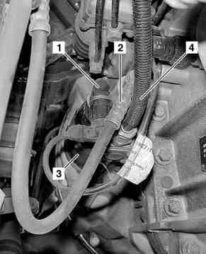
T25.20-0029-02
1 Clutch release travel sensor
2 Clutch operator hydraulic line
3 Clutch servo assistance
4 Clutch booster pneumatic line
| Remove/install | ||
Danger! | Risk of poisoning caused by swallowing brake fluid. Risk of injury caused by brake fluid coming into contact with skin and eyes. | Pour brake fluid only into suitable and appropriately marked containers. Wear protective clothing and eye protection when handling brake fluid. | |
1 | Release compressed air from ancillary consumer circuit | Use the drain valve on the ancillary consumer reservoir to do this. | |
2 | Detach lower engine compartment paneling | Only perform the steps necessary for removing the engine compartment paneling under the transmission. | |
3 | Disconnect electrical connector on clutch release travel sensor (1) | Installation: When replacing the clutch booster (3) or parts of the clutch, the clutch release travel must be newly stored in the drive control (FR) control unit. | |
4 | Detach clutch operator hydraulic line (2) from the clutch booster (3) | Collect escaping fluid with a suitable container. | |
| Notes on handling brake fluid | All models | |
5 | Detach compressed-air connector of clutch booster pneumatic line (4) from clutch booster (3) | On "VOSS 230" compressed-air connector. | |
On "VOSS 232" (NG 8, NG 12) or "Schäfer SDF" (NG 6) compressed-air connector. | |||
6 | Detach clutch booster (3) from transmission | The clutch booster (3) is secured with two bolts. | |
Installation: Ensure that the plunger is seated correctly in the clutch booster (3). | |||
7 | Install in the reverse order | ||
8 | Bleed clutch operating system | ||
| Clutch actuation - replace brake fluid | ||
| Notes on handling brake fluid | All models | |
9 | Perform function test on clutch |
Henviste dokumenter
- ah4250p000101a Oplysninger om bremsevæske
- ap2520t2981ca
- ar4210w0900a Af-, påmontering af stikforbindelse trykluftrør
- ar4210w0900c Afmontering, montering af stikkobling trykluft
- ar6120t1105ca
- as4250z000101a Risiko for forgiftning ved indtagelse af bremsevæske. Risiko for hud- og øjen-skader ved kontakt med bremsevæske