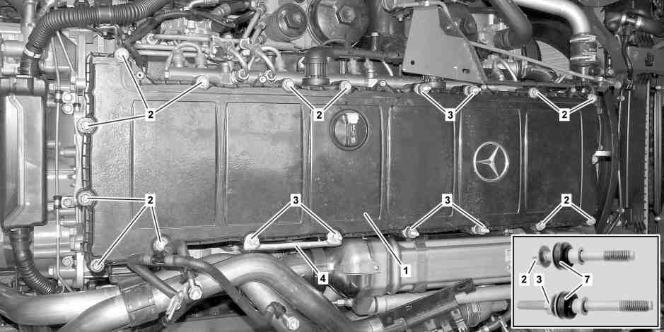
W01.20-1055-09
Shown on engine 470.9 |
1 | Cylinder head cover | 3 | Bolts | 7 | Decoupling disc | ||
2 | Bolts | 4 | Heat shield |
Warning | Risk of accident from vehicle starting off by itself when engine running. Risk of injury (bruises and burns) resulting from working on the engine while it is being started or when it is running. | Secure vehicle to prevent it from starting off by itself. Wear closed and snug-fitting work clothes. Do not touch hot or rotating parts. | |
Warning | Risk of injury to skin and eyes suffering scalding from contact with hot coolantspray. Risk of poisoning from swallowing coolant. | Do not open cooling system unless coolant temperature is below 90 °C. Open cap slowly and release the pressure. Do not pour coolant into beverage containers. | |
Caution | Risk of injury to skin and eyes due to handling of engine oil. Risk of poisoning caused by swallowing engine oil | Wear protective gloves, protective clothing and safety glasses. | |
Topical note | Notes on self-locking nuts and bolts | ||
Topical note | Notes on avoiding damage through contamination and foreign objects | ||
Notes on compressed air connection systems | |||
| Remove | ||
1 | Drain coolant at expansion reservoir. | Only in case of expansion reservoir at rear. | |
2 | Remove heat shield (4). | ||
3 | Disconnect air intake line of compressor on resonator box. | If required. | |
See information from body manufacturer. | |||
4.1 | Remove bracket on cylinder head cover (1). | For the expansion reservoir at the rear. | |
4.2 | Disconnect air intake line of compressor on resonator box. | For the expansion reservoir at the front. | |
5 | Remove resonator box. | If required. | |
6 | Check contoured gasket of cylinder head cover (1) for leaks. | If no leakage is determined, the profiled seal of the cylinder head cover (1) can be reused. | |
7 | Check contoured gasket of intermediate frame for leaks. | Only for engine 470.9 up to engine end number 222433, or for engine 471.9 up to engine end number 124618 | |
If no leakage is determined, the profiled seal of the cylinder head cover of the intermediate frame can be reused. | |||
8 | Remove the cylinder head cover (1). | The screw/bolts (2, 3) are secured against falling out in the cylinder head cover (1). | |
9 | Remove intermediate frame. | Only if the profile seal of the intermediate frame is leaky. | |
Only for engine 470.9 up to engine end number 222433 or engine 471.9 up to engine end number 124618 | |||
| Install | ||
10 | Perform visual check to check decoupling disks (7) on screws (2, 3). | If there is a problem, | |
| |||
Install new screws/bolts (2, 3) with new decoupling discs (7). | |||
11 | Install new contoured gasket in intermediate frame. | Only for engine 470.9 up to engine end number 222433 or for engine 471.9 up to engine end number 124618 | |
12 | Install intermediate frame. | Only if intermediate frame was removed. | |
Only for engine 470.9 up to engine end number 222433 or engine 471.9 up to engine end number 124618 | |||
13 | Install new contoured gasket in cylinder head cover (1). | Only if a leak was determined at the contoured gasket of the cylinder head cover (1). | |
14 | Install cylinder head cover (1). | The screw/bolts (2, 3) are secured against falling out in the cylinder head cover (1). | |
Screw/bolt, cylinder head cover to camshaft case | |||
15 | Install heat shield (4). | Nut, bracket to bolt for cylinder head cover with intermediate frame | |
16 | Install resonator box. | Only if the resonator was removed. | |
Screw/bolt, compressor air intake duct clamp to cylinder head cover bracket | |||
Screw/bolt, vent line to oil separator | |||
17.1 | Attach bracket to cylinder head cover (1). | For the expansion reservoir at the rear. | |
17.2 | Attach air intake line of compressor to resonator box. | For the expansion reservoir at the front. | |
18 | Fill expansion reservoir with coolant. | Only in case of expansion reservoir at rear. | |
See information from body manufacturer. | |||
| Clean | ||
19 | Clean cylinder head cover (1) and intermediate frame around the whole circumference. | ||
| Check | ||
20 | Start engine and perform an engine test run. | See information from body manufacturer. | |
21 | Stop engine and check for leaks in area of cylinder head cover (1) and intermediate frame. | Visual inspection. |
Henviste dokumenter
- ah0000n000101a Oplysninger om selvlåsende bolte og møtrikker
- ah0000n500001h Oplysninger om forebyggelse af skader på grund af snavs og fremmedlegemer
- ah0018n000101a Oplysninger om trykluftstikforbindelsessystemer
- ar0120g5016n
- as0000z000501a Fare for ulykke ved automatisk igangsætning når motoren kører. Fare for personskade på grund af knusning og forbrænding, hvis der arbejdes mens motoren startes eller kører
- as1800z000101a Fare for personskade på hud og øjne ved håndtering af motorolie. Fare for forgiftning ved indtagelse af motorolie
- as2000z000101a Risiko for skoldningsskader på hud og øjne pga. sprøjtende, varm kølervæske. Risiko for forgiftning ved indtagelse af kølervæske