
W09.30-1019-09
Shown on ENGINE 902.9 |
1 | Charge air pipe | 4 | Air intake hose | 7 | Electrical line (circuit 31) | ||
2 | Electrical line (circuit 30) | 5 | Air intake pipe | 8 | Wiring harness actuation | ||
3 | Current clamp | 6 | Power supply wiring harness | R21 | Charge air preheating system heating element |

9 | Decade resistor |
10 | Engine cover |
11 | Electrical connection (on coolant temperature sensor (B65)) |
W09.41-1074-11
Danger ! | Risk of explosion from explosive gas. Risk of poisoning and caustic burns from swallowing battery electrolyte. Risk of injury through burns to skin and eyes from battery acid or when handling damaged lead-acid batteries | No fires, sparks, open flames or smoking. Wear acid-resistant gloves, clothing and glasses. Only pour battery acid into suitable and appropriately marked containers. | |
Danger ! | Risk of injury caused by body parts being pinched or crushed as cab is tilted | Ensure that no one is within the tilting range of the cab as it is being tilted. Always tilt the cab all the way to the end position and secure with the safety strut. | |
| Notes on battery | ||
| Notes on tilting the cab | ||
| Remove | ||
1 | Disconnect battery ground line | ||
| |||
2 | Remove batteries | ||
3 | Tilt cab | ||
4 | Remove engine cover (10) over the injection lines | ||
5 | Remove black charge air hose on charge air pipe (1) | ||
6 | Remove charge air pipe (1) without mounting flange for the charge air preheating system heating element (R21) | ||
7 | Remove air intake hose (4) | ||
8 | Seal openings on air intake pipe (5) and ATL | ||
| Install | ||
9 | Install charge air pipe (1) with mounting flange for the charge air preheating system heating element (R21) | ||
10 | Attach black charge air hose on charge air pipe (1) | Clamp, charge air hose to charge air manifold/charge air pipe and charge air cooler | |
11 | Insert charge air preheating system heating element (R21) into charge air pipe (1) | The mounting bolts should be installed first in operation step 14, by routing and connecting up the power supply wiring harness (6). | |
12 | Install relay for charge air preheating system heating element (R21) | ||
Nut, electrical line for terminal 30 to relay for intake air preheating heating element | |||
13 | Clip on actuation wiring harness (8) for charge air preheating system heating element (R21) | ||
14 | Route and connect up power supply wiring harness (6) for charge air preheating system heating element (R21) | ||
Screw/bolt, intake air preheating heating element to charge air pipe | |||
Nut, electrical line for terminal 30 to intake air preheating heating element | |||
Nut, electrical line for terminal 30 to relay for intake air preheating heating element | |||
15 | Install engine cover (10) | ||
16 | Install air intake hose (4) | ||
17 | Connect ground line to battery | ||
| |||
18 | Connect diagnostic system | ||
19 | Parameterize MR/PLD control unit | ||
| |||
| Check | ||
20 | Disconnect electrical connection (11) at coolant temperature sensor (B65) | ||
21 | Adjust decade resistor (9) to 10 kΩ | This simulates a coolant temperature of -12°C. | |
Ohm decade | |||
22 | Connect decade resistor (9) to electrical connection (11) | Ohm decade | |
Electrical connection kit | |||
23 | Connect current clamp (3) to the electrical line (2) | ||
24 | Switch on ignition and measure power consumption | The current display of approx. 70 to 75 A is shown for 5 to 10 s and the charge air preheating system heating element (R21) must noticeably heat up. | |
25 | Switch off ignition | ||
26 | Remove decade resistor (9) and current clamp (3) | ||
27 | Connect electrical connection (11) to coolant temperature sensor (B65) | ||
28 | Tilt back cab | ||
29 | Connect diagnostic system, start XENTRY and perform quick test | There must be no fault codes in the processed control unit. If necessary, process any fault codes in other control units, subject to separate repair order. | |
30 | End XENTRY and remove diagnostic system | ||
Update Vehicle Documentation (VeDoc) | |||
31 | Code M90 (Charge air preheating system, electric), supplement on the data card. | ||
32 | Document retrofitted equipment | Hang the following note under field organization text on the KG09: |
Charge air pipe/charge air cooling |
Number | Designation | Engine 900.9 in model 375, 970, 972, 975, 976 | Engine 924.9 in model 958, 970, 972, 974, 975, 976 | |
BA09.41-N-1010-01B | Clamp, charge air hose to charge air manifold/charge air pipe and charge air cooler | Nm | 8 | 8 |

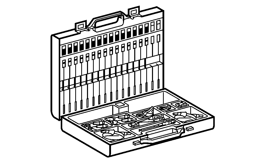
124 589 09 63 00
Ohm decade
220 589 05 99 00
Electrical connection kit
Parts ordering note |
Part no. | Designation | Quantity |
All models | ||
A 000 159 54 04 | Intake air preheating heating element (grid heater) | 1 |
A 000 540 55 08 | Electrical wiring harness (actuation) | 1 |
A 001 546 96 41 | Terminal block for cable cross section up to 2.5 mm2 | 1 |
N 000000 001877 | Nut M8 | 1 |
N 000137 008212 | WasherM8 | 1 |
A 001 997 94 90 | Cable tie small | n. B. |
A 002 997 24 90 | Cable tie large | n. B. |
A 655 545 08 83 | Upper part cap | 1 |
A 655 545 09 83 | Lower part cap | 1 |
A 000 540 69 27 | Electrical line (for terminal 30 line from battery over fuse to relay) | 1 |
A 001 545 39 80 | Seal (for terminal 30 line from battery over fuse to relay) | 2 |
A 014 545 91 26 | Receptacle (for terminal 30 line from battery over fuse to relay) | 1 |
N 046234 008000 | Cable lugM8 (for terminal 30 line from battery over fuse to relay) | 2 |
A 003 545 70 01 | Fuse box | 1 |
A 002 545 17 83 | Protective cap | 1 |
N 000000 004219 | Fuse | 1 |
Model 970, 972, 974, 975, 976 with 4 cylinder engines | ||
A 924 098 16 07 | Charge air pipe | 1 |
A 000 159 75 04 | Parts kit, for vehicles with code F07 (Cab S (short), but without code Y19 (Stowage box, on frame) | 1 |
A 000 159 76 04 | Parts kit, for vehicles with code F04(Cab L (long)) or with code F07 (Cab S (short)) and with code Y19 (Stowage box, on frame). Not for model 974.262/263. | 1 |
A 000 159 77 04 | Parts kit, for vehicles with code F04(Cab L (long)) or with code F07 (Cab S (short)) and with code Y19 (Stowage box, on frame). Only for model 974.262/263. | 1 |
Model 970, 972, 974, 975, 976 with 6 cylinder engines | ||
A 906 090 07 42 | Charge air pipe | 1 |
A 000 159 78 04 | Parts kit, for vehicles with code F07 (Cab S (short), but without code Y19 (Stowage box, on frame). | 1 |
A 000 159 79 04 | Parts kit, for vehicles with code F04(Cab L (long)) or with code F07 (Cab S (short)) and with code Y19 (Stowage box, on frame). Not for model 974.262/263. | 1 |
A 000 159 80 04 | Parts kit, for vehicles with code F04(Cab L (long)) or with code F07 (Cab S (short)) and with code Y19 (Stowage box, on frame). Only for model 974.262/263. | 1 |
Henviste dokumenter
- ah5410p000101a
- ah5410p000101a Oplysninger om batterier
- ah6080n000301a Oplysninger om tipning af førerhus
- an0930w000201gh
- an5418w001201gh
- an5418w001301gh
- ar0715w162804gh
- ar0715w162804gh
- ar5410w0003a Afbrydelse, tilslutning af batteriets stelledning
- as5410z000101a Brand-/eksplosionsfare på grund af kortslutning og udsivende knaldgas. Forbrændingsfare/fare for personskade ved ætsning af øjne, hud og sliminder på grund af batterielektrolyt/-tåge, kortslutning og lysbuepåvirkning. Fare for
- as6080z000101a Fare for personskade ved fastklemning og knusning, når førerhuset tippes