40 - 7501.01 Axle base and frame measurement
Checking front axle
Preceding work:
Removing spare wheel and spare wheel bracket (40-3481)

R Wheelbase SV Front axle track width SH Rear axle track width k1 Front reference bores k2 Central reference bores K Reference bore in measuring bridge | V1 - V4 Axle base measurements at front axle H1 - H3 Axle base measurements at rear axle BR1 - BR4 Measurements of frame width |
Measurement data in mm
Measurement points | Permissible difference between left and right | Effective distance measurement |
Front axle | ||
V1 From reference bore "k2" in frame side member to outer hexagon bolt of forward front spring mounting on opposite frame side member | 4 | - |
V2 From reference bore "k2" in frame side member to outer hexagon bolt of forward front spring | - | 1900 +2 1) - 6 |
V3 From reference bore "K" in measuring bridge to outer hexagon bolt of forward front spring mounting | 3 | - |
1) Permissible deviation between left and right 3 mm.
2) When the front axle is removed from the vehicle, the distance "V4" from reference bore "k2" to reference bore "k1" in the frame side member may be measured instead of the distance "V1". The reference distance corresponds to distance "V2".


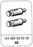
Special tools
Note
The additional axle base and frame measurement procedure is intended to follow normal wheel adjustment work on accident vehicles or on vehicles where an accident is suspected.
This procedure is based on the wheelbase measurements.
Assessment criteria are the differences between left and right or the effective distance measurement. The vertical parallelism and frame alignment can then be checked in the case of minor frame damage, and when the axle base measurements are insufficient for a clear diagnosis, i.e. if it cannot be decided whether repairs on the Celette frame straightening bench are necessary or not.

Checking front axle
1 Measure distance "V1" from reference bore "k2" in frame side member on left and right sides using (06) and measuring pin with probe ((013g) length 250 mm) and measuring pin with ring ((013d) length 205 mm).
(06) 124 589 02 19 00
(013d;g) 601 589 03 63 00
V1, V2 Measurement point on frame side member

V1, V2, V3 Measurement points on front axle
2 Using the same tools, measure distance "V2" from reference bore "k2" in frame side member to outer hexagon bolt of forward spring mountings on left and right sides.
3 If the front axle is removed, instead of distance "V2" measure distance "V4" from reference bore "k1" in frame side member. To do this, use the measuring pin with probe (length 275 mm) on the forward measuring point and the measuring pin with probe (length 250 mm) on the rear measuring point.

Note
Three different diameters (15, 16 and 17 mm) of locating pin (013b) are available to firmly locate the measuring bridge without play. The diameter of each is stamped on the head of the pin.

4 Locate measuring bridge (013a) through reference bores "k2" in frame side members and fasten whilst pressing the bridge firmly against the frame side members.
Note
Remove underbody protection on the contact surfaces.
(013a) 601 589 03 63 00

5 Insert retaining pins (013c) for (06) into measuring bridge (013a) and attach (06).
6 Measure distance "V3" from reference bore "K" in measuring bridge to outer hexagon bolt of forward spring mounting on left and right sides using (06) and measuring pin with ring (length 205 mm).
(06) 124 589 02 19 00