07.1-8014 Removing and Installing Injection Timer
Preceding work: Vacuum pump removed (43-0618). | Operation no. of operation texts and work units or standard texts and flat rates: 07-8014 |

Cylinder head cover | detach, attach. |
Engine or crankshaft | position on 15° ATDC. |
Camshaft gear (154) and timing device (18) | fix in position to timing chain with hose strap. |
Chain tensioner (156) | remove, install (05-310). Tightening torque 80 Nm. |
Screw (153) for camshaft gear | unscrew, screw in. Tightening torque 45 Nm. Note washer (152). |
Camshaft gear (154) | remove, install. |
Central fastening bolt (19) | unscrew, screw on, tightening torque Check washer (20), renew if necessary. |
Locking pin (151) | withdraw with threaded pin (116 589 01 34 00) and impact puller (116 589 20 33 00). |
Mounting basket (18a) | remove, install. |
Timing chain (155) | press to the outside with metal strips (approx. 0.570120) and withdraw timing device (18) with universal pliers. |
Timing device (18) | remove, install. Note If the roller or bearings of the piston vacuum pump are damaged, check whether the drive flange with cam at the injection timing device (18) is damaged. Replace part, if necessary. |
Screw plug with seal (11) | unscrew from injection pump (1). |
Injection pump | turn with serrated wrench (027) and lock in position with locking bolt (023). Remove locking bolt. |
Engine or crankshaft | crank 1 revolution by hand and check TDC setting on crankshaft and camshaft. |
Start of delivery | check (07.1-112), set if necessary (07.1-117). |

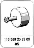
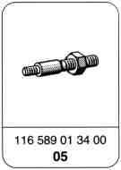


Special tools
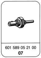
Note
Engines 602.962, 603.960/963/971
Segment flange of injection timing device modified from forging to sintered part.
Production breakpoint: as of July 1994
Model | Engine | Engine end no. Manual transmission | Engine end no. Automatic transmission |
124.128/188 | 602.962 | 032205 | 020081 |
124.133/193 | 603.960 | 052378 | |
124.333/393 | 603.963 | 004453 | |
140.134 | 603.971 | 012299 | |

Removal and Installation
1 Remove cylinder head cover.
2 Turn engine to 15° ATDC of no. 1 cylinder.

3 Fix camshaft gear and injection timer in place with cable strap.
Camshaft gear

4 Remove chain tensioner (156) for relieving the load on the timing chain (05-310).

5 Unscrew bolt for camshaft gear on camshaft; hold crankshaft in place when performing this step.
Tightening torque 45 Nm.
Remove camshaft timing gear.

6 Unscrew central fastening bolt (19); hold crankshaft in place when performing this step.
Left-hand thread
7 Withdraw locking pin (arrow) and remove mounting basket.
Impact extractor Special tool 116 589 20 33 00
M6 threaded pin Special tool 116 589 01 34 00
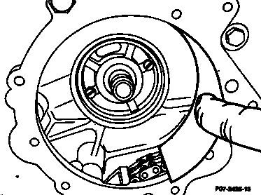
8 Press timing chain out of the way with metal strips and use universal pliers to withdraw ignition timer.
Shop-made metal strips
Thickness approx. 0.5 mm
Length approx. 140 mm
Width approx. 070 mm
Note
If the roller or bearings of the piston vacuum pump are damaged, check whether the drive flange with cam at the injection timing device (18) is damaged. Replace part, if necessary.

9 Unscrew plug (11).

10 Use serrated wrench (027) to turn injection pump on injection pump camshaft until the lug of the governor is visible in the hole. In this position, push in locking bolt (023) until it is felt to engage and tighten union nut by hand.
027 Serrated wrench
Special tool 601 589 00 08 00

11 Install injection timer. Tighten central fastening bolt to 40-50 Nm.
Left-hand thread
12 Remove locking bolt (023) otherwise the injection pump will be damaged when engine is first started.
13 Assemble engine.
14 Test start of delivery with digital tester
(07.1-112), set if necessary (07.1-117).
023 Locking bolt
Special tool 601 589 05 21 00