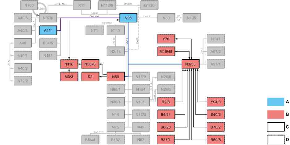
S07.10-0034-79
Shown without code FX9 (KEYLESS GO) and MJ8 (ECO start/stop function) |
A1/1 | Instrument cluster (KI) control unit | N93 | Central gateway (CGW) | |
B2/8 | Hot film mass air flow sensor | N118 | Fuel system control unit (FSCU) | |
B4/14 | Rail pressure sensor | S2 | Ignition lock switch | |
B6/23 | Camshaft Hall sensor | S40/3 | Clutch pedal switch | |
B37/4 | Accelerator pedal module | Y76 | Fuel injectors | |
B50/5 | Fuel temperature sensor | Y94/3 | Quantity control valve | |
B70/2 | Crankshaft Hall sensor | CAN HMI | User interface CAN | |
M3/3 | Fuel pump with fuel feed module | CAN V | Vehicle CAN | |
M16/45 | Throttle valve actuator | A | Mercedes-Benz | |
N3/33 | CDI control unit | B | Nissan | |
N50 | Fuse and relay module control unit (SRM) | C | Default | |
N50k8 | Fuel pump relay | D | Optional |

S07.10-0035-79
Shown with code FX9 (KEYLESS GO) and MJ8 (ECO start/stop function) |
A1/1 | Instrument cluster (KI) control unit | N93 | Central gateway (CGW) | |
B2/8 | Hot film mass air flow sensor | N118 | Fuel system control unit (FSCU) | |
B4/14 | Rail pressure sensor | S2/3 | KEYLESS GO start/stop button | |
B6/23 | Camshaft Hall sensor | S40/3 | Clutch pedal switch | |
B37/4 | Accelerator pedal module | Y76 | Fuel injectors | |
B50/5 | Fuel temperature sensor | Y94/3 | Quantity control valve | |
B70/2 | Crankshaft Hall sensor | CAN HMI | User interface CAN | |
M3/3 | Fuel pump with fuel feed module | CAN V | Vehicle CAN | |
M16/45 | Throttle valve actuator | A | Mercedes-Benz | |
N3/33 | CDI control unit | B | Nissan | |
N10/1 | Signal acquisition and actuation module (SAM) control unit | C | Default | |
N50 | Fuse and relay module control unit (SRM) | D | Optional | |
N50k8 | Fuel pump relay |
Function requirements for fuel supply, general points
Circuit 15 ON (ignition ON)
Circuit 87 ON (engine management ON)
Fuel supply, general points
The fuel supply supplies filtered fuel out of the fuel tank in adequate amounts under all operating conditions at an adequate pressure to the fuel injectors (Y76).
Function sequence for fuel supply
The function sequence for fuel supply is described in the following steps:
Function sequence for fuel pump actuation
Function sequence for fuel low-pressure circuit
Function sequence for fuel system high-pressure circuit
Function sequence for safety fuel shutoff
Function sequence for fuel pump actuation
To switch on the fuel pump with fuel feed module (M3/3), the fuse and relay module (SRM) control unit (N50) sends a signal to the relay fuel pump (N50k8) and then to the fuel system control unit (FSCU) (N118).
The fuel system control unit (FSCU) (N118) actuates the fuel pump with fuel feed module (M3/3) with a direct signal. The fuel system control unit (FSCU) (N118) also receives the signal "Fuel specified pressure" from the CDI control unit (N3/33).
Function sequence for fuel low-pressure circuit
The fuel low-pressure circuit consists of the following components:
Fuel tank
Fuel pump with fuel feed module (M3/3)
Fuel lines
Fuel filter
Quantity control valve (Y94/3)
Fuel system high pressure pump, low-pressure side
Fuel temperature sensor (B50/5)
The fuel system control unit (FSCU) (N118) evaluates the current fuel pressure, compares it with the fuel specified pressure and actuates the fuel pump with fuel feed module (M3/3) in such a way that the actual pressure corresponds to the specified pressure.
During actuation the fuel pump with the fuel feed module (M3/3) module suctions the fuel out of the fuel feed module and pumps it through the fuel filter to the fuel system high pressure pump. Depending on the fuel requirement, the fuel pressure is regulated to about 5.0 bar through the pressure limiting valve integrated into the fuel system high pressure pump.
The quantity control valve (Y943) also regulates the supply of fuel to the fuel system high pressure pump (feed quantity) depending on the engine operating point in order to keep the fuel temperature low.
Any fuel not required flows back into the fuel tank through the return line.
Function sequence for fuel system high-pressure circuit
The fuel high-pressure circuit consists of the following assembly parts:
Fuel system high pressure pump
Rail
High-pressure lines
High pressure fuel pressure sensor
Fuel injectors (Y76)
The fuel system high pressure pump pumps the fuel into the rail as a function of the signal from the accelerator pedal module (B37/4), the engine rpm and the fuel temperature.
From the rail, the fuel flows through the high-pressure lines to the fuel injectors (Y76). The fuel injectors (Y76) spray fuel in a fine atomized form.
The CDI control unit (N3/33) calculates the injection quantity selectively for each cylinder according to a characteristics map for the respective operating condition. The injection quantity depends on the fuel pressure in the rail and the actuation time of the fuel injectors (Y76).
The fuel pressure in the rail is controlled by the quantity control valve (Y94/3). The actual fuel pressure in the rail is detected by the rail pressure sensor (B4/14). The fuel temperature is detected via the fuel temperature sensor (B505). Both pieces of information are passed on permanently to the CDI control unit (N3/33).
Function sequence for safety fuel shutoff
The safety fuel shutoff system is designed to ensure traffic and occupant safety.
The CDI control unit (N3/33) actuates the safety fuel shutoff based on the following signal:
Crankshaft Hall sensor (B70/2), engine rpm
The safety fuel shutoff is activated by the CDI control unit (N3/33) under the following condition:
Absence of the engine speed signal
If the engine speed signal is missing, the fuel pump is switched off.