Commercially available tools


D26.50-0028-01
D26.50-0027-01
1 Clamp transmission main shaft in a vise with protective jaws (input end uppermost).
2 Remove circlip (45) and take off thrust plate (44).
3 Remove 5th gear gearwheel (43) and needle roller bearing (42).


D26.50-0030-01
D26.50-0123-01
4 Remove synchronizer cone (46) and synchronizer ring (41).
5 Remove circlip (40).


D26.50-0124-02
6 Remove reverse gear wheel together with shift sleeve and synchronizer body (33-39).
7 Remove needle bearing (32).
8 If necessary, press shift sleeve (35) off synchronizer body (39) and remove sliding blocks (36), compression springs (38) and balls (37).
The balls are spring-loaded. Cover synchronizer assembly with a suitable cloth when disassembling.
D26.50-0127-02

D26.50-0012-01
9 Turn transmission main shaft around.
10 Remove circlip (4).


D26.50-0128-02
11 Remove 3rd gear wheel together with synchronizer cone, synchronizer ring, synchronizer body and shift sleeve (5-11, 47).
12 Remove needle bearing race (12).
13 If necessary, press shift sleeve (5) off synchronizer body (9) and remove sliding blocks (6), compression springs (8) and balls (7).
The balls and sliding blocks are spring-loaded. Cover synchronizer assembly with a suitable cloth when disassembling.
D26.50-0129-02

D26.50-0017-01
14 Remove circlip (13).

15 Remove 2nd gear wheel (15) together with thrust plate (14).
If necessary, use puller . Position puller on stepped edge to shift splines of 2nd gear gearwheel.
16 Remove needle bearing race (16).
D26.50-0120-03

D26.50-0021-01
D26.50-0020-01
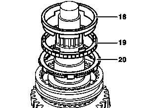
17 Remove synchronizer cone (18), synchronizer
ring (19) and synchronizer cone (20).
18 Remove circlip (17).


19 Remove 1st gear wheel together with all remaining components above it (21-29).
Use puller
20 Remove needle bearing race (30).
21 If necessary, press shift sleeve (21) off synchronizer body (25) and remove sliding blocks (24), compression springs (23) and balls (22).
The balls are spring-loaded. Cover synchronizer assembly with a suitable cloth when disassembling.
D26.50-0121-03
D26.50-0122-03