
1 | Control cylinder |
2 | Control plunger |
3 | Sealing ring with double groove |
4 | Control rod |
5 | Fork pin |
6 | Screw-in plug |
7 | Spring |
8 | Spring |
9 | Lock pin |
10 | Assembly tool (to install the control rod) |
11 | Compensating washer |
B62 | Stroke sensor of the GV (SSP) (for code (GS2) electro-pneumatic gear shift control or in code (GE3) Mercedes PowerShift |
W26.35-1004-06
| Remove | ||
1 | Remove the GV stroke sensor (B62) | Only vehicles with code (GS2) electro-pneumatic gear shift control or with code (GE3) Mercedes PowerShift. | |
2 | Remove the command cylinder (1) |
| |
3 | Remove the threaded plug (6), the springs (7) and ( 8) and lift out the lock pin (9) | The threaded plug (6) is under spring tension. | |
4 | Remove both pins from the fork (5) | Extraction claw | |
Impact extractor | |||
5 | Pull the control rod (4) with the shift piston (2) | To remove, displace the control fork and turn the control rod (4). | |
6 | Remove the sealing ring with double groove (3) | ||
Warning | Risk of injury. Skin or eye injuries may result when handling hot or glowing objects. | Wear protective gloves, protective clothing and safety glasses, if necessary. | |
7 | Heat up the control piston (2), remove the control rod (4) and lift the shim out (11) | Heat to approx. 80 °C. | |
Puller | |||
Retaining device | |||
8 | Remove radial seal and guide bushing from control rod (4) |
| |
| Adapter for removing guide bush in front section of transmission housing | ||
Internal extractor | |||
Counter stay | |||
| Install | ||
9 | Install radial seal and guide bushing of control rod (4) |
| |
Apply synthetic grease. | |||
Synthetic grease 50 g | |||
Drift | |||
10 | With the assembly tool (10), install the control rod (4) and engage the shift fork () on the control rod (4) | ||
| Assembly tool for installing splitter group shift rod | ||
Utilizing a screwdriver, engage the shift fork in the control rod (4) through the pin left side hole of the bearing (5). | |||
11 | Install the pins of the fork (5) | Apply chemical lock on the fork's pin (5). | |
Sealant - Loctite 242 | |||
Transmission 715.517/527Selection fork retaining pin in the gearbox | |||
Transmissions 715.372/382/388/531/535Selection fork retaining pin in the gearbox | |||
12 | Install the threaded plug (6), with the springs (7) and ( 8) and the lock pin (9) | Apply chemical lock on the threaded plug (6). | |
Loctite 5203 surface sealant | |||
Transmission 715.517/527Blocking of the demultiplier group on the housing | |||
Transmissions 715.372/382/388/531/535Blocking of the demultiplier group on the housing | |||
13 | Determine the compensating washer (11) for the shift piston (2) |
| |
Transmissions 715.372/382/517/527/531/535Splitter group control piston adjustment dimension | |||
14 | Pull the control rod (4) with the assembly tool (10) out against stop | ||
| Assembly tool for installing splitter group shift rod | ||
15 | Install the determined compensating washer (11) over the control rod (4) | ||
16 | Place the double groove ring (3) on the shift piston (2) and install on the control rod (4) | Lock the shift piston (2) with chemical lock. | |
Apply synthetic grease on the double groove ring (3). | |||
Thread locking adhesive, Loctite 241 | |||
Grease | |||
Transmission 715.517/527Fastening of the splitter group control piston | |||
Transmissions 715.372/382/388/531/535Fastening of the splitter group control piston | |||
Puller | |||
17 | Determine shim for control cylinder (1) |
| |
Apply synthetic grease. | |||
Grease | |||
.Splitter group control cylinder adjustment dimension | |||
Internal extractor | |||
Counter stay | |||
18 | Install the GV stroke sensor (B62) | Only vehicles with code (GS2) electro-pneumatic gear shift control or with code (GE3) Mercedes PowerShift. | |
Gearboxes 715.517/527Additional group sensor in the gearbox | |||
Gearboxes 715.372/382/388/531/535Splitter box sensor in the transmission |
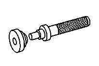


714 589 05 15 00
Drift
715 589 06 33 00
Extraction claw
000 589 30 33 00
Internal extractor
715 589 02 07 00
Puller


715 589 00 31 00
Retaining device
000 589 33 33 00
Counter stay
000 589 34 33 00
Counter stay
355 589 01 63 00
Impact extractor

000 589 27 33 00
Internal extractor
Repair materials |
Number | Designation | Order number |
BR00.45-Z-1027-06A | Synthetic grease 50 g | A 001 989 32 51 10 |
BR00.45-Z-1117-06A | Grease | Molykote DC 33 leicht |
BR00.45-Z-1120-01A | Sealant - Loctite 242 | A 003 989 31 71 |
BR00.45-Z-1129-02A | Loctite 5203 surface sealant | Henkel AG & Co. KGaA |
BR00.45-Z-1131-02A | Thread locking adhesive, Loctite 241 | A 002 989 70 71 |
Odkazované dokumenty
- ar2618b1000ta
- ar2635b100001a
- ar2635b100002ta
- ar2635b100003ta
- as0000z000201a Nebezpečí poranění kůže nebo očí při zacházení s horkými nebo žhavými předměty
- wf5850b100001a
- wf5850b263501a