
1 | Range group cylinder |
2 | Shift piston |
3 | Right bearing bolt |
4 | Left bearing bolt |
5 | Breather cap |
6 | Screw plug |
7 | Spring |
8 | Catch bolt |
9 | Piston rod |
A | Marking |
G26.31-3125-06

13 | Internal extractor |
14 | Counter stay |
W26.31-1013-01

10 | Radial shaft sealing ring |
11 | Pilot bushing |
12 | Drift |
W26.31-1012-01
Warning | Risk of injury. Skin or eye injuries may result when handling hot or glowing objects. | Wear protective gloves, protective clothing and safety glasses, if necessary. | |
Notes on compressed air connection systems | |||
| Remove | ||
1 | Detach compressed-air lines from range group cylinder (1). | ||
2 | Remove range group cylinder (1). | ||
3 | Remove breather cap (5) and screw plug (6); remove spring (7). | The screw plug (6) is spring-loaded. | |
4 | Pull out catch bolt (8) max. 40 mm out of transmission housing central section. | To prevent the interlock bar from springing out. | |
5 | Mark installation position of shift piston (2). | Marking (arrow A) on shift piston (2) in "12 o'clock position". | |
6 | Remove left bearing pin (4) and use a small screwdriver through the threaded hole of the left bearing pin (4) to prevent the shift fork from falling. | Use a screwdriver with max. Ø 6 mm. | |
7 | Remove transmission bolt from right bearing pin (3). | ||
8 | Remove right bearing pin (3). | ||
9 | Rotate shift piston (2) with piston rod (9) through 180° and pull out. | ||
10 | Remove pilot bushing (11) using internal extractor (13) and counter stay (14). | Counter stay | |
Internal extractor | |||
11 | Remove radial shaft sealing ring (10) using internal extractor (13) and counter stay (14). | Counter stay | |
Internal extractor | |||
| Install | ||
12 | Grease radial shaft sealing ring (10) slightly and install up to contact using drift (12). | The spring lock washer of the radial shaft sealing ring (10) must point inward (oil side). | |
Synthetic grease 50 g | |||
Drift | |||
13 | Install pilot bushing (11) up to contact using drift (12). | Drift | |
14 | Install shift piston (2) with piston rod (9). | The marking (A) on the shift piston (2) must be in the "12 o'clock position". | |
15 | Hook shift fork into piston rod (9). | Using a small screwdriver though the tapped hole of the bearing bolt on the left (4), hook in the shift fork. | |
16 | Coat thread of right bearing pin (3) with sealant and install right bearing pin (3). | Loctite 5203 sealant | |
Shift fork bearing pin at transmission housing | |||
17 | Coat thread of left bearing pin (4) with sealant and install left bearing pin (4). | Loctite 5203 sealant | |
Shift fork bearing pin at transmission housing | |||
18 | Screw in transmission bolt securely at right bearing pin (3). | Bolt, transmission housing rear section to transmission housing center section | |
19 | Install range group cylinder (1). | ||
20 | Press catch bolt (8) fully into transmission housing central section and insert spring (7). | To make it easier to install the screw plug (6), shift the range group using a compressed-air gun. | |
21 | Tighten screw plug (6) and install breather cap (5). | | |
Range group shift rod lock to transmission housing | |||
22 | Attach compressed-air lines at range group cylinder (1). |
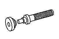


714 589 05 15 00
Drift
000 589 33 33 00
Counter stay
000 589 27 33 00
Internal extractor
Odkazované dokumenty
- ah0018n000101a Pokyny k systémům konektorových spojů tlakového vzduchu
- ar2618g3100ae
- as0000z000201a Nebezpečí poranění kůže nebo očí při zacházení s horkými nebo žhavými předměty