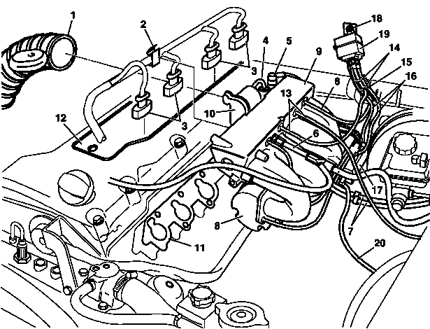
1 | Air intake hose |
2 | Mounting clip |
3 | Injection valve connector |
4 | Air pump switchover valve |
5 | Purge control valve |
6 | Vacuum line |
7 | Fuel line |
8 | Air pump |
9 | Intake manifold |
10 | Idle speed control actuator |
11 | Intake manifold gasket |
12 | Cylinder head cover trim panel |
13 | Vacuum line |
14 | Cable tie |
15 | Electrical connector |
16 | Hoses |
17 | Gas distributor |
18 | Screw |
19 | Pressure sensors |
20 | Gas hose |
D09.20-1016-06
Danger | Risk of explosion due to escaping combustible gas or overheating of gas cylinders.Risk of injury caused by burns to skin and eyes. Risk of frostbite to body parts caused by escaping gas and by touching components near the valves when emptying gas cylinders. Risk of poisoning or suffocation caused by inhaling gas. | Remove any sources of ignition. | |
Warning | Risk of accident from vehicle starting off by itself when engine running. Risk of injury (bruises and burns) resulting from working on the engine while it is being started or when it is running. | Secure vehicle to prevent it from starting off by itself. Wear closed and snug-fitting work clothes. Do not touch hot or rotating parts. | |
| Remove/install | ||
1 | Empty lines after solenoid valve liquid phase |
| |
2 | Detach vacuum line (13) on the intake manifold (9) | Installation: Replace hose clamps. | |
3 | Disconnect electrical connectors (15) | ||
4 | Remove hose (16) for entry pressure to gas distributor (17) | Hose, entry pressure to gas distributor | |
Tool kit | |||
5 | Remove hoses (16) for exit pressure on gas distributor (17) | Hose, exit pressure to gas distributor | |
Tool kit | |||
6 | Remove screw/bolt (18) and take off pressure sensors (19) | Screw/bolt, pressure sensor to firewall | |
7 | Remove gas hose (20) at gas distributor (17). | Gas hose at gas distributor elbow fitting | |
Tool kit | |||
8 | Disconnect electrical connections to gas distributor (17) | ||
9 | Disconnect battery ground line | ||
10 | Remove air intake hose (1) | ||
11 | Remove idle speed control actuator (10) | ||
12 | Remove air pump switchover valve (4) | ||
13 | Remove purging switchover valve (5) | ||
14 | Release retaining clip (2) at cylinder head cover and unplug injection valve connectors (3) of the injection valves at the intake manifold (9) | ||
15 | Remove trim panel for cylinder head cover (12) | ||
Bolt, trim panel of cylinder head cover to cylinder head cover | |||
Danger | Risk of death when working on component parts and systems with U >= 30 V alternating voltage (AC) or U >= 60 V direct voltage (DC) | Do not touch damaged or defective live component parts and lines or non-insulated electrical connections and lines. | |
16 | Unplug the connector from the primary side of ignition coils, and run the lines out of the housing of the cylinder head cover | The lines are included with the other lines in a subharness and passed downwards through the intake manifold (9). | |
17 | Detach vacuum lines (6) from intake manifold (9) | ||
Vacuum line at intake manifold vacuum fitting | |||
Tool kit | |||
18 | Remove air pump (8) from the bracket | Do not disconnect lines of the air pump (8). | |
Danger | Risk of explosion caused by fuel igniting, risk of poisoning caused by inhaling and swallowing fuel as well as risk of injury to eyes and skin caused by contactwith fuel. | No fires, sparks, open flames or smoking. Pour fuels into suitable and appropriately marked containers only. | |
19 | Detach fuel lines (7) at engine | ||
20 | Remove intake manifold (9) from cylinder head | ||
Installation: First insert outer screw/bolt on cylinder 4 and then fasten the hose on injection fitting. | |||
Intake manifold to cylinder head | |||
21 | Install in the reverse order | ||
| Check | ||
22 | Check gas distributor (17) with hoses (16), pressure sensors (19) and the injection fitting for leaktightness | ||
23 | Document the work in an inspection logbook |

000 589 10 99 00
Tool kit
Odkazované dokumenty
- ar0120d501402c
- ar0754d0002a
- ar0754d0002a
- ar0910d8030f
- ar0920d131006b
- ar0920d131007e
- ar1430d7255a
- ar3022d1152b
- ar4725d0019a
- ar4725d0019a
- ar4725d100001d
- ar4730d8220a
- as0000z000501a Nebezpečí úrazu při samovolném rozjetí vozidla při běžícím motoru. Nebezpečí poranění pohmožděním a popálením při výkonech prováděných během startování nebo při běžícím motoru
- as0000z001801a Nebezpečí výbuchu vlivem úniku hořlavých plynů nebo přehřátí plynových nádrží. Nebezpečí poranění popálením kůže a očí. Nebezpečí omrznutí částí těla v důsledku unikajícího plynu a při dotyku se součás
- as0000z003501a Nebezpečí ohrožení života při pracích na součástech a systémech se střídavým napětím U >= 30 V (AC), resp. se stejnosměrným napětím U >= 60 V (DC)
- as4700z000101a Nebezpečí výbuchu při vznícení, nebezpečí otravy při vdechnutí a požití paliva inebezpečí úrazu v důsledku přímého doteku kůže a očí s palivem