40 - 7501.06 Axle base and frame measurement
Checking frame alignment
Preceding work:
Removing spare wheel and spare wheel bracket (40-3481)


k2 Reference bore in frame side member K Reference bore in measuring bridge FV Locating bore in 1st frame cross member (front axle) FH Locating bore in 7th frame cross member (rear axle) "a" Frame alignment deviation 013a Measuring bridge (component of the measurement bracket set) |
Data (frame alignment) | ||
Permissible deviation at reference bore "K" in measuring bridge when locating bores "FH" and "FV" are in alignment 1) | with wheelbase 3050 mm 4.0 mm | |
with wheelbase 3350 4.5 mm | ||
with wheelbase 3700 5.5 mm | ||
1) Vehicle aligned horizontally in the lateral direction.

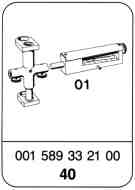
Special tools
Note
The additional axle base and frame measurement procedure is intended to follow normal wheel adjustment work on accident vehicles or on vehicles where an accident is suspected.
This procedure is based on the wheelbase measurements.
Assessment criteria are the differences between left and right or the effective distance measurement.
The vertical parallelism and frame alignment can then be checked in the case of minor frame damage, and when the axle base measurements are insufficient for a clear diagnosis, i.e. if it cannot be decided whether repairs on the Celette frame straightening bench are necessary or not.
A check of the frame alignment is particularly important for vehicles that have been involved in a diagonal collision. During the measurement, however, the frame-floor unit must not have any skew whatsoever laterally to the direction of travel, otherwise there may be errors in the measurements.

Arrangement of measuring tools
k2 Reference bore in frame side member K Reference bore in measuring bridge FV Locating bore in 1st frame cross member (front axle) FH Locating bore in 7th frame cross member (rear axle) "a" Frame alignment deviation 013a Measuring bridge (component of the measurement bracket set) 014a Front part of test equipment with measuring cord and alignment bob 014b Central part of test equipment with alignment bob 014c Rear part of test equipment with measuring bob |

Checking frame alignment
1 Check the position of the vehicle in the lateral direction. To do this, insert the spirit level (09) in the measuring bridge (013a) which is attached to the frame side member and is located via reference bore "k2".
Note
If necessary, balance the higher side with the opposite side by adding an appropriate weight.
(09) 001 589 33 21 00
(013a) 601 589 03 63 00

2 Center rear part of frame alignment test equipment with alignment bob (014b) on 7th frame cross member with the aid of locating bore "FH" and fasten in place.

(014b) 601 589 03 63 00

3 Center front part of frame alignment test equipment (014a) on 1st frame cross member with the aid of locating bore "FV" and loosely fasten in place.
(014a) 601 589 03 63 00

4 Thread measuring cord of front part of equipment (014a) to rear part (014b). Adjust front and rear parts so that there is only just a gap between the alignment bob and the measuring cord. Secure measuring cord on rear part.
The front and rear parts of the test equipment must be accurately adjusted, otherwise there will be a considerable error in the measurement.
(014a;b) 601 589 03 63 00

5 Insert central part of test equipment with measuring bob (014c) into reference bore "k" in measuring bridge (013a) and fasten with the wing nut.
6 Measure alignment deviation (distance "a") between measuring bob (014c) and measuring cord (014a).
Note
To check the measurement, suspend the measuring bob left and right of the measuring cord to avoid any measurement error due to a displacement of the cord by the bob.