15-705 Function of preglow system
A. General
Combustion in the diesel engine is by way of self-ignited fuel injected into the highly compressed and consequently severely heated-up combustion air.
If the engine is cold, the self-igniting temperature is not reached by compression alone. A preglow system is therefore required whose duty it is to increase the temperature of the compressed air and to allow the engine to start by inflaming fuel particles on the glow plugs.
The duration of the preglowing process is dependent on the ambient temperature.

Construction of the quick-start pencil-type glow plugs
The main components of the pencil-type glow plugs are a housing with screw-in thread
M 121.25 and a heater pin pressed into the housing.
The single-pole connection pin is secured to the housing by means of a permenant brass round nut connection.
The pencil-type glow plugs are designed for a voltage of 11.5 V and are operated in parallel.

The heater element consists of a series-connected heater and control coil.
1 Control coil
2 Heater coil

When the glow system is switched on, a current of approx. 30 A flows for each glow plug. The heater coil heats up the glow plug very rapidly. The control coil resistance increases with rising temperature, limiting the current to approx. 8-16 A. This serves as an overload protection for the glow plug.
Current curve of the quick-start pencil-type glow plug

A heater pencil temperature of 900 °C is reached after a glowing period of 9 seconds, while the maximum temperature of 1180 °C is reached after 30 seconds.
Temperature curve of the quick-start pencil-type glow plug
Cable harness for preglow system engine 601.911 with mechanical transmission
Plastic intake manifold necessitates lengthening ground cable and routing from intake manifold to fuel filter.
Production breakpoint: September - October 1990
Model | Engine | Engine end no. Manual transmission from to |
201.122 | 601.911 | 347517 - 348400 |
Production breakpoint: March - October 1991
Model | Engine | Engine end no. Manual transmission from to |
201.122 | 601.911 | 362537 - 381504 |
Standard production breakpoint: as of January 1992
Model | Engine | Engine end no. Manual transmission |
201.122 | 601.911 | 389421 |
B. Quick-start preglow system

Wiring diagram model 201.122/126
F1 | Central electrics |
R9 | Glow plugs |
W9 | Ground, front left (near headlamp unit) |
e | X35 Terminal block terminal 30/terminal 61 (battery) |
A1e16 | Preglow indicator in instrument cluster |
N14 | Preglow time-delay relay a Power relay b Electronic unit c Temperature sensor (NTC resistor) d Reed relay |
Note
1 pencil-type glow plug line 2.5 sw/gn omitted on engine 601

Wiring diagram models 124.120/125/180/185
W9 | Ground, front left (near headlamp unit) |
a | X49/1 Connector backup light switch |
b | Fuse 7, terminal 15 (unprotected) |
c | X4 Terminal block terminal 30 (fuse/relay box) |
A1e16 | Preglow indicator in instrument cluster |
N14 | Preglow time-delay relay a Power relay b Electronic unit c Temperature sensor (NTC resistor) d Reed relay |
R9 | Glow plugs |
X26 | Connector interior/engine 12-pole |
Note
1 pencil-type glow plug line 2.5 sw/gn omitted on engine 601.

Wiring diagram models 124.130/330/190/393
W9 | Ground, front left (near headlamp unit) |
a | X49/1 Connector backup light switch |
b | Fuse 7, terminal 15 (unprotected) |
c | X4 Terminal block terminal 30 (fuse/relay box) |
A1e16 | Preglow indicator in instrument cluster |
N14 | Preglow time-delay relay a Power relay b Electronic unit c Temperature sensor (NTC resistor) d Reed relay |
R9 | Glow plugs |
X26 | Connector interior/engine 12-pole |

Preglow time-delay relay
The preglow time-delay relay is installed in the engine compartment on the left wheel arch.
After removing the protective cap the electrical connections and the 80-A fuse are accessible.
Model 201
An NTC resistor in the preglow time-delay relay registers the relay ambient temperature.
Functions of the preglow time-delay relay
The preglow time-delay relay has the following functions:
Switching the glow current
Ready-for-starting indication
Safety cut-out
Fault indication
Note
With unfavorable tolerances of the pencil-type glow plugs or the Reed relay (d) it is permissible that the fault indication responds only if twopencil-type glow plugs R9 are defective.
The fault indication (monitoring of pencil-type glow plugs) is effected by comparing the current of the 1st pencil-type glow plug with the current of the 2nd to 5th pencil-type glow plugs connected in parallel.

Engines 601, 602
The currents of the two lines to the pencil-type glow plugs 1 and 2-5 are directed via two counterwound Reed relay windings with different numbers of windings.
With identical current flow in both windings the magnetic fields cancel each other, the Reed contact does not respond.

If the equilibrium of the magnetic fields is disturbed by the failure of one or several pencil-type glow plugs, the Reed contact closes and the electronics unit (b) is activated.
The preglow indicator lamp switches off immediately, consequently no longer lighting up at the start of the preglowing process.
On engine 603 the 6th pencil-type glow plug is monitored separately and the fault indicated upon failure of this pencil-type glow plug.
Engine 603
Glow current control
When actuating the key in position "2" (preglowing, driving) the preglow time-delay relay (voltage) on terminal 15 is switched on. The power relay (a) closes the power circuit from terminal 30 (plus) via the fuse to the pencil-type glow plugs.
If the key is turned to position "3" (start), the power relay (a) remains attracted, activated by terminal 50. The glowing process is continued until the key is returned to position "2".
Ready-for-starting indication
A temperature sensor installed in the preglow time-delay relay determines the glow period.
The preglow indicator lamp in the instrument cluster lights up when the glow system is switched on.

If the required glow time, dependent on the ambient temperature of the preglow time-delay relay, has been reached, the preglow indicator lamp goes out, in this way indicating readiness for starting.
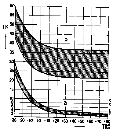
Preglowing time
Safety cut-out
If a start fails to take place within 20-25 seconds after the readiness for starting has been indicated, the glow current is interrupted by the safety cut-out. If the engine is started thereafter, the glow system is again switched on for the duration of the starting process.
The safety cut-out is no longer fixed. It is determined from the time up to readiness for starting (the preglow indicator lamp goes out) plus 20-35 seconds.
a Preglowing time
b Safety cut-out
Fault display
A fault in the preglow system is indicated by failure to light up of the preglow indicator lamp when actuating the key in position "2".
The following faults are registered:
- Interruption of the line to the connection terminal 30.
- 80-A fuse defective.
- Power relay in the preglow time-delay relay defective.
- Interruption of one or several lines to the pencil-type glow plugs.
- Interruption of one or several pencil-type glow plugs.
C. Preglow system with afterglowing
The preglow system has been changed with regard to the previous system in the following points:
Preglow time-delay relay
Coolant temperature sensor
Pencil-type glow plugs

Preglow time-delay relay
Preglowing time
The preglowing time until the preglow indicator lamp goes out is dependent on the coolant temperature (see diagram).
Preglowing time t in seconds
Coolant temperature T in °C

Afterglowing time
In order to improve the warming-up characteristics the glowing process is continued with running engine as a function of the coolant temperature.
a) Version MJ 88
Afterglowing time up to a maximum of 17 s (see diagram)
Afterglowing time t in seconds
Coolant temperature T in °C

b) Version MJ 89, MJ 89,
MJ 89 MJ 89, MJ 89, code 830
Afterglowing time up to a maximum of 60 s (see diagram)
Afterglowing time t in seconds
Coolant temperature T in °C
Standard production breakpoint: January 1989 (preglow system with afterglowing)
Model | Engine | Engine end no. manual transmission | Engine end no. automatic transmission |
124.120 124.180 | 601.912 | 119226 | 009930 |
124.125 124.185 | 602.912 | 127975 | 019037 |
124.130 124.190 | 603.912 | 048192 | 031795 |
124.133 124.193 | 603.960 | -- | 017932 |
124.330 | 603.913 | 000563 | 000573 |
124.333 124.393 | 603.963 | -- | 000847 |
201.122 201.126 | 601.911 602.911 | 292358 073017 | 023518 014820 |
460.3 | 602.930 | 001556 | -- |
Monitoring of glow plugs
The glow plugs are monitored individually by a microprocessor in the preglow time-delay relay.
In addition, the glow plugs are constantly monitored during vehicle operation by a low test current. Failure of one or several glow plugs is indicated if the preglow indicator lamp lights up for approx. 1 minute with the engine running.
Fault indication by preglow indicator lamp
Lamp fails to light up even during preglowing, lights up for approx.1 minute while driving.
Fault: One or several glow plugs defective.
Lamp fails to light up during preglowing and also while driving.
Fault: Indicator lamp defective, line interruption to the indicator lamp, preglow time-delay relay defective.
Lamp lights up permanently.
Fault: Preglow time-delay relay defective (relay sticking).
Lamp fails to light up, engine is hard to start or fails to start altogether.
Fault: Short circuit on one or several glow plugs, line interruption, preglow time-delay relay defective.
Protection of preglow current circuit
Instead of the 80-A fuse an electronic cut-out has been installed. If a short circuit occurs the power circuit is interrupted. After the short circuit has been eliminated, the fuse of the relay is restored to the operational state by turning the key in the steering lock back to "0".
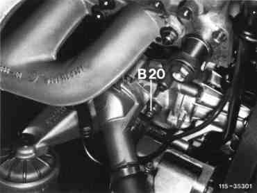
Coolant temperature sensor
A coolant temperature sensor (B20) or (B11/8) is installed to control the preglow and afterglow times.
Arrangement engines 601, 602
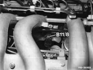
Arrangement engine 603
Pencil-type glow plugs
For afterglowing, pencil-type glow plugs with three different heater tube lengths are installed (see Checking preglowing 15-711).
Wiring diagram engine 601.911 Model year 1988
Model year 1989 code 830

A1e16 | Instrument cluster preglow indicator |
B20 | Temperature sensor (preglowing) |
F1 | Central electrics |
N14 | Preglow time-delay relay |
R9 | Glow plugs |
W9 | Ground, front left (near headlamp unit) |
X25 | Connector preglow cable harness |
a | X35 Terminal block terminal |
Wiring diagram engine 601.912 Model year 1988
Model year 1989 code 830

X4 | Terminal block terminal 30 (fuse and relay box) |
X25 | Connector preglow cable harness |
X26 | Connector interior/engine 12-pole |
X49/2 | Connector starter lockout and backup light switch |
a | S2/2 Glow starter switch terminal 50 |
b | K1 Overvoltage protection relay jack 3 (only with air conditioner) |
c | X27 Connector starter cable harness jack 2 |
A1e16 | Instrument cluster preglow indicator |
B20 | Temperature sensor (preglowing) |
F1 | Fuse and relay box |
N14 | Preglow time-delay relay |
R9 | Glow plugs |
S16/1 | Starter lockout and backup light switch (only with automatic transmission) |
W1 | Main ground (behind instrument cluster) |
W9 | Ground, front left (near headlamp unit) |
Wiring diagram engine 602.911 model year 1989 code 830

R9 | Glow plugs |
W9 | Ground, front left (near headlamp unit) |
X25 | Connector preglow cable harness |
a | X35 Terminal block terminal 30, terminal 61 (battery) |
A1e16 | Instrument cluster preglow indicator |
B20 | Temperature sensor (preglowing) |
F1 | Central electrics |
N14 | Preglow time-delay relay |
Wiring diagram engine 602.912 model year 1989 code 830

W9 | Ground, front left (near headlamp unit) |
X4 | Terminal block terminal 30 (fuse and relay box) |
X25 | Connector preglow cable harness |
X26 | Connector engine cable harness |
X49/2 | Connector starter lockout and backup light switch |
a | S2/2 Glow starter switch (terminal 50) |
b | Overvoltage protection relay (jack 3) |
c | X27 Connector starter cable harness jack 2 |
A1e16 | Instrument cluster preglow indicator |
B20 | Temperature sensor (preglowing) |
F1 | Fuse and relay box |
N14 | Preglow time-delay relay |
R9 | Glow plugs |
S16/1 | Starter lockout and backup light switch (only with automatic transmission) |
W1 | Main ground (behind instrument cluster) |
Wiring diagram engine 603.912 Model year 1988
Model year 1989 code 830

W9 | Ground, front left (near headlamp unit) |
X25 | Connector preglow cable harness |
X26 | Connector engine cable harness |
X49/2 | Connector starter lockout and backup light switch |
a | Terminal block X4 (terminal 30) |
b | Glow starter switch S2/2 (terminal 50) |
c | Overvoltage protection relay (jack 3) |
d | X27 Connector starter cable harness jack 2 |
A1 | Instrument cluster |
e16 | Preglow indicator |
p1 | Coolant temperature gauge |
B11/8 | Coolant temperature sensor |
F1 | Fuse and relay box |
N14 | Preglow time-delay relay |
R9 | Glow plugs |
S16/1 | Starter lockout and backup light switch (only with automatic transmission) |
W1 | Main ground (behind instrument cluster) |