13-7001 Disassembling and assembling compressor

A Compressor with 90 mm piston diameter
1 Hexagon bolt, intermediate plate | 30 Nm. |
2 Hexagon bolt, cylinder head | 30 Nm. |
3 Cylinder head | |
4 Gasket | replace. |
5 Hexagon bolt | 15 Nm. |
6 Spacer bush | |
7 Bracket | |
8 Washer | |
9 Pressure plate | |
10 Intermediate plate | |
11 Suction plate | |
12 Gasket | replace. |
13 Cylinder liner | |
14 Hexagon bolt | 30 Nm. |
15 Spring lock washer | |
16 Piston ring | |
17 Piston ring | |
18 Piston ring | |
19 Circllip | |
20 Piston pin | |
21 Piston | |
22 Gasket | replace. |
23 Conrod bolt | 30 Nm. |
24 Conrod with conrod bearing | |
25 Flange | |
26 Bush | |
27 Seal | replace. |
28 Crankshaft with bearing disc | |
29 Bearing cap | |
30 Hexagon bolt | 50 Nm. |
31 Roller bearing with bearing disc | |
32 Input gear | |
33 Hexagon bolt | screw tight with ring wrench socket 442 589 00 03 00, 270 Nm. This corresponds to an actual value of 360 Nm. |

B Compressor with 100 mm piston diameter
46 Hexagon bolt, cylinder head | 30 Nm. |
47 Hexagon bolt, cylinder head | 30 Nm. |
48 Cylinder head | |
49 Gasket | replace. |
50 Hexagon nuts | 15 Nm. |
51 Valve plates | |
52 Pressure valve plates | |
53 Intermediate plate | |
54 Suction valve plate |
55 Gasket | replace. |
56 Cylinder liner | |
57 Gasket | replace. |
58 Piston ring | |
59 Piston ring | |
60 Piston ring | |
61 Circlip | |
62 Piston | |
63 Piston pin | |
64 Hexagon bolt | 60 Nm. |
65 Outer bearing flange | |
66 O-ring | replace. |
67 Bearing bush | check, replace. |
68 Crankshaft | 30 Nm. |
69 Conrod | |
70 Bearing bush | |
71 Inner bearing flange | |
72 Hexagon bolt | 30 Nm. |
73 Input gear | |
74 Hexagon bolt | screw tight with ring wrench socket 442 589 00 03 00, 270 Nm. This corresponds to an actual value of 360 Nm. |
Data
Compressor dia. 100 mm 90 mm
Bore diameter 100,030 90,030
100,000 89,990
Piston diameter 99,955 89,950
99,915 89,910
Piston play 0,075 0,080
0,095 0,100
Piston pin diameter 20,000 20,000
19,995 19,995
Piston pin play - conrod 0,020 0,020
0,038 0,038
Compressor dia. 100 mm 90 mm
Pirston pin play - piston 0,003 0,003
0,013 0,013
Crankshaft journal dia. 43,975 31,975
43,956 31,959
Crankshaft bearing play (axial 0,050 0,050
0,150 0,150
Crankshaft bearing play (radial) 0,030 0,040
0,101 0,082
Conrod bearing play (axial) 1 cylinder 0,100 0,065
0,600 0,217
2 cylinder - 0,100
0,286
Conrod bearing play (radial) 0,025 0,027
0,057 0,073
Distance to suction plate (1 cyl. three-ring piston) 1,350 -
0,510
Piston ring gap clearance | Piston ring end clearance | |
Compressor dia. 90 mm Groove I II III |
0,035 0,055 0,025 0,040 |
0,020 0,052 0,020 0,052 |
Compressor dia. 100 mm Groove I II III |
0,020 0,040 0,020 0,040 |
0,015 0,040 0,020 0,055 |
Piston stands back/projects (from upper edge of cylinder liner)
1 cylinder dia. 90 mm | - 0,40 to - 1,20 |
2 cylinder dia. 90 mm | - 1,90 to - 2,70 |
1 cylinder dia. 100 mm | 0,09 to - 0,71 |
Tightening torques Nm
Power steering pump to timing case | 60 |
Bearing cap to timing case | 25 |

Deliveries
A Compressor 2 cyl. dia. 90 mm
B Compressor 1 cyl. dia. 100 mm
C Compressor 1 cyl. dia. 90 mm
D Engine speed
E Compressor speed


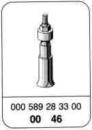
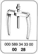
Special tools


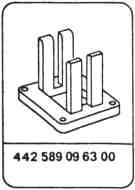

Note
When installing a new compressor or reconditioned engine, check the cross-section of the compressor pressure line for signs of coking.
If a constriction exists, the pressure lines, pressure regulator and the four-circuit protection valve must be replaced.
A Compressor with 90 mm piston diameter
Disassembling
-------------------------------
1 Unscrew coolant feed and return lines (arrows).
Special wrench 000 589 07 03 00
2 Detach compressed air line (35) and suction line (36).

3 Detach cylinder head (3) together with intermediate plate.

4 Unbolt cylinder liner (arrows) and take off over the piston.

5 Remove circlip (19) for piston pin (20).
6 Press out piston pin (20) and take off piston.

7 Take off side cover (39).

8 Remove conrod (24) and take off together with bearing cap and bearing shells.

9 Remove power steering pump (37) and take off driven plate (38).

10 Take off timing case cover (40).

11 Fit on blocking device over the crankshaft and screw tight.
Note
The crankshaft must be turned sufficiently until the journal is facing up.
Blocking device 442 589 09 63 00

12 Unscrew hexagon bolt at input gear (32) with ring wrench socket and take out input gear (32) together with hexagon bolt.
Ring wrench socket 442 589 00 03 00
13 Take off blocking device.

14 Use an assembly lever to press the crankshaft (28) out of the bearing and take off the bearing flange (25).
Note
When pressing out the crankshaft, the roller bearing inner race must be held tight (arrow) to prevent the inner race dropping out into the timing case.

15 Remove locking plate (29) for bearing.

16 Pull out bearing (31) using internal puller and shop-made supporting plate.
Internal puller 000 589 28 33 00
Spindle from counter-suppert 000 589 34 33 00

17 Remove bearing bush from bearing flange using a drift.
Drift 363 589 03 15 00

18 Unscrew hexagon bolt (1) from the cylinder head.

19 Take off cylinder head gasket (12) and suction valve plate (11).
20 Take off intermediate plate (10) and gasket (4).

21 Take pressure valve plate (9) off the intermediate plate.

Assembly
-------------------------------
1 Install bearing bush (26) in the bearing flange (25) and ream with a reamer to the size
30,041 .
30,020
Note
The oil drillings in the bearing bush (26) and in the bearing flange (25) must be aligned.
Drift 363 589 03 15 00

2 Bolt roller bearing with 2 metal plates (arrow) to prevent it dropping out.

3 Fit on roller bearing so that the collar of the bearing inner race is facing the fan.
4 Install roller bearing in the bearing cap.
Drift 198 589 03 39 00
5 Remove metal plates again.
6 Install locking plate (29), 50 Nm.

7 Fit loose bearing plate onto the crankshaft with the chamfer (arrow) facing the main journal.

8 Counter-hold bearing inner race and install crankshaft (28).

9 Replace O-ring (27).
10 Oil bearing flange (25) at the fit and O-ring (27), place onto the housing and onto the crankshaft. The oil drillings (arrows) in the housing and in the bearing flange (25) must be aligned.

11 Install bearing flange (25) by tightening the hexagon bolts (arrows) evenly.
12 Remove hexagon bolts again.

13 Fit on input gear (32) with hexagon bolt.
14 Fit on blocking device over the crankshaft and screw tight.
Blocking device 403 589 01 63 00

15 Screw hexagon bolt of input gear tight, 270 Nm.
Note
This value corresponds to an actual torque of 360 Nm.
16 Torque wrench (40), ratchet (41) and ring wrench socket (42) must be in a line.
Ring wrench socket (42) 442 589 00 03 00
17 Take off blocking device.
18 Fit on power steering pump (37) with new
O-ring and driven plate (38), 60 Nm.

19 Insert conrod bearing shells into conrod cover and conrod. The oil drillings (arrows) in the conrod bearing and in the conrod must be aligned.
20 Markings (43) on the conrod cover and (44) on the conrod must be aligned.
21 Install conrod (24) with conrod cover and bearing shells, 30 Nm.
22 Fit on piston over the conrod and install piston pin (20) and circlip (19).
23 Fit gasket for the cylinder liner onto the timing case.

24 Position piston ring gaps offset 120° (arrows).

25 Compress piston rings with tensioning pliers until the tensioning strap can still just be moved.
26 Fit on cylinder liner over the piston and press in.
Tensioning pliers 000 589 20 61 00
27 Bolt cylinder liner (arrows) onto timing case, 25 Nm.

28 Fit pressure valve plate (9) onto the intermediate plate and insert washer (8) into the recess (arrow) of the pressure plate.
29 Fit valve plate (7) onto the pressure valve plate (9) with the curved side facing up, and bolt tight, 15 Nm.
30 Fit intermediate plate (10) with new gasket (4) onto the cylinder head and screw hand-tight.
31 Fit suction valve plate (11) and cylinder head gasket (12) over the locking pins with the designation "Top" facing the suction valve plate.

32 Screw hexagon bolts for cylinder head (3) and hexagon bolt (1) for intermediate plate tight, 30 Nm.
33 Bolt end cover (39) tight onto timing case with new gasket, 25 Nm.
34 Install timing case cover and seal (01-8000).
35 Bolt on coolant feed and return lines (arrows).
Special wrench 000 589 07 03 00
36 Fit on compressed air line (35) and suction line (36).

B Compressor with 100 mm piston diameter
Disassembling
-------------------------------
1 Remove charge air pipe (09-8661).
2 Unbolt coolant feed and return lines (arrows).
Special wrench 000 589 07 03 00
3 Detach compressed air line (75).

4 Unscrew hexagon bolts (46) for compressor.

5 Take off cylinder head (48) together with intermediate plate.

6 Take off cylinder liner (56).

7 Remove circlip (61) for piston pin (63).
8 Press out piston pin (63) and take off piston.

9 Remove power steering pump (37) and take off driven plate (38).

10 Remove timing case cover (76) upward.
11 Take off side cover (39).

12 Fit blocking device over the conrod or over the crankshaft, respectively, and bolt tight.
Note
The crankshaft must be turned sufficiently until the journal together with conrod is facing up.
Blocking device 442 589 09 63 00

13 Unscrew hexagon bolt at input gear (73) with ring wrench socket and take out input gear (73) together with hexagon bolt.
Special wrench 442 589 00 03 00
14 Take off blocking device.

15 Use an assembly lever to press the crankshaft (68) together with conrod (69) out of the bearing bush and take off the outer bearing flange (65).
16 Remove crankshaft (68) together with conrod (69) upward.

17 Take inner bearing flange (71) off the timing case.

18 Use a suitable drift to remove bearing bush from the inner bearing flange.
19 Use a suitable drift to remove bearing bush from the outer bearing flange.

20 Take gasket (55) and suction valve plate (54) off the intermediate plate and cylinder head, respectively.

21 Unscrew hexagon bolt (47) and take cylinder head together with gasket (49) off the intermediate plate (53).

22 Unscrew hexagon nuts (50).
23 Take off valve plates (51) and pressure valve plates (52).

Assembling
-------------------------------
1 Use a suitable drift to install bearing bush (67) in the outer bearing flange (65). If necessary, ream bearing bush with a reamer to the size
38,035 .
37,980
Note
The oil drillings in the bearing bush (67) and in the bearing flange (65) must be aligned (arrows).

2 Use a suitable drift to install bearing bush (70) in the inner bearing flange (71). If necessary, ream bearing bush with a reamer to the size
38,035 .
37,980
Note
The groove (arrow) of the split bearing bush must be facing upward when installed.
3 Install inner bearing flange (71), 30 Nm.
4 Install crankshaft together with conrod from above.

5 Replace O-ring (66).
6 Oil outer bearing flange (65) at the fit and O-ring (66).
7 Fit bearing flange (65) onto the housing and onto the crankshaft. The oil drillings (arrows) in the housing and in the bearing flange (65) must be aligned.

8 Install bearing flange (65) by tightening the hexagon bolts (arrows) evenly.
9 Unscrew hexagon bolts again.

10 Fit on input gear (73) with hexagon bolt.
11 Fit blocking device over the conrod and over the crankshaft, respectively, and bolt tight.

12 Tighten hexagon bolt of input gear, 270 Nm.
Note
This value corresponds to an actual torque of 360 Nm.
13 Torque wrench (77), ratchet (78) and ring wrench socket (79) must be in a line.
Special wrench (79) 442 589 00 03 00
14 Take off blocking device.
15 Fit on power steering pump (37) with new O-ring
and driven plate (38), 60 Nm.
16 Fit piston over the conrod, install piston pin (63) and circlip (61).
17 Fit gasket for the cylinder liner onto the timing case.
18 Position piston ring gaps offset 120° (arrows).

19 Compress piston rings with tensioning pliers until the tensioning strap can still just be moved.
20 Fit on cylinder liner over the piston and press in.
Tensioning pliers 000 589 20 61 00
21 Fit on pressure valve plates (52) and valve plates (51) and bolt tight, 15 Nm.
Note
Pressure valve plates (52) and valve plates (51) must lock in place.

22 Bolt cylinder head (48) and new gasket (49) hand-tight to intermediate plate (53).
23 Fit suction valve plate (54) and cylinder head gasket (55) over the locking pins with the designation "Top" facing in direction of suction valve plate.
24 Fit on cylinder head (48) over the cylinder liner.

25 Screw hexagon bolts (46) for compressor and hexagon bolt (47) for intermediate plate tight, 30 Nm.
26 Bolt end cover (39) with new gasket onto timing case, 25 Nm.
27 Install timing case cover and seal (01-8000).
28 Bolt on coolant feed and return lines (arrows).
Special wrench 000 589 07 03 00
29 Fit on compressed air line (75).
30 Install charge air pipes (09-8661).