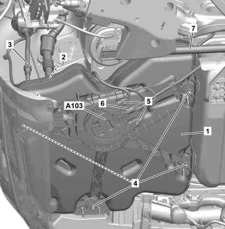
Example illustration |
1 | AdBlue® tank |
2 | Filler neck |
3 | Vent line |
4 | Bolts |
5 | Electrical connectors |
6 | AdBlue® line |
P14.40-2656-12
Warning | Risk of burn injuries and scalding when working at AdBlue lines and the components attached to them. Risk of injury to skin and eyes when handling AdBlue. Risk of poisoning caused by swallowing AdBlue | Pour AdBlue into suitable containers only. Wait until the pressure is released before starting any work on the exhaust aftertreatment system. | |
Topical note | Notes on avoiding damage through contamination and foreign objects | ||
| Remove/install | ||
1 | Empty AdBlue® tank (1). | ||
2 | Remove filler neck (2) and bleed line (3) from AdBlue® tank (1). | ||
3 | Remove cover under AdBlue® tank (1). | Installation: Only install cover under AdBlue® tank (1) after leak test. | |
4 | Remove AdBlue® line (6) from AdBlue® tank (1), collect escaping AdBlue® with suitable container and seal connections with clean protective covers. | Set of protective covers | |
5 | Release electrical connections (5) and disconnect. | ||
6 | Unscrew screws (4) and remove AdBlue® tank (1). | Aid of helper required. | |
Bolt, AdBlue® tank to body | |||
7 | Install in the reverse order. | ||
| Check | ||
8 | Check AdBlue® tank (1) and connections for leaktightness. | If leaks are present, | |
| |||
Replace corresponding component. | |||
9 | Install cover under AdBlue® tank (1). | ||
10 | Connect vehicle diagnosis system and enter fill level of AdBlue® tank (1) in AdBlue® control unit. | ||
|

001 589 01 91 00
Set of protective covers