AR49.10-P-7280VT | Remove / install exhaust system from flange connection | 17.10.11 |
ENGINES 113.989 in MODEL 171.473

P49.10-2462-01
1 Rear diagonal strut
2 Bolt
3 Bolt
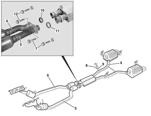
P49.10-2463-06
4 Exhaust system
5 Left catalytic converter
6 Right catalytic converter
7 Bolts
8 Exhaust rubber mount
9 Retaining clip
10 Seal
11 Seal
12 Bolts
| Remove/install | ||
Danger! | Risk of death caused by vehicle slipping or toppling off of the vehicle lift. | Align vehicle between columns of vehicle lift and position the four support plates at vehicle lift support points specified by vehicle manufacturer. | |
Danger! | Risk of injury to skin and eyes caused by handling hot or glowing objects. | Wear safety gloves, protective clothing and safety glasses, if necessary. | |
Danger! | Risk of injury caused by scraping or cutting body parts on sharp vehicle parts | Always wear protective gloves when working on or near sharp and non-deburred vehicle parts. Deburr repair panels. | |
| Notes on self-locking nuts and bolts | All models | |
1 | Lift/jack up vehicle | Position arms of lift platform in such a way that bolt (3) of the rear diagonal strut (1) on the right and left is accessible. | |
2 | Remove rear diagonal strut, (1) on the right and left | Installation: Bolt (2) and bolt (3) of the diagonal struts may only be tightened when the vehicle is standing with its wheels on the ground. | |
| |||
3 | Support catalytic converter on the left (5) and catalytic converter on the right (6) with the transmission jack and transmission platform | Transmission jack | |
Transmission platform for passenger cars and commercial vehicles gotis://A_25/35/49_02.0 | |||
4 | Remove exhaust system (4) from left catalytic convertor (5) and right catalytic convertor (6) by unscrewing bolts (7, 12) | Installation: Clean connecting points free of combustion and corrosion residues. Replace seal (10, 11) and bolts. | |
| |||
5 | Unhook exhaust system (4) from exhaust rubber mount (8) and remove | To simplify removal: Apply liquid lubricant to the retaining bracket (9) and on the holes of the exhaust rubber mounts. | |
Check exhaust rubber mount for wear, replace if required. | |||
Lubricant paste | |||
6 | Install in the reverse order | ||
7 | Check installation position and unobstructed movement of exhaust system (4) | The exhaust system must be installed free of stress, if necessary: Align exhaust system. | |
Danger! | Risk of accident caused by vehicle starting off by itself when engine is running. Risk of injury caused by contusions and burns during starting procedure or when working near the engine as it is running | Secure vehicle to prevent it from moving by itself. | |
8 | Carry out engine test run | Inspect exhaust system for leaks. |
Frame floor assembly
Number | Designation | Model 171 | |
BA61.10-P-1005-01A | Self-locking bolt, rear diagonal strut to frame floor | Nm | 60 |
Exhaust system
Number | Designation | Engine | |
BA49.10-P-1002-01A | Bolt, flange connection to exhaust pipe | Nm | 20 |
Repair materials
Number | Designation | Order number |
BR00.45-Z-1002-06A | Antifriction paste, rubber parts 2.5 kg, DB supply specification 6867.00 | A 000 989 01 60 |