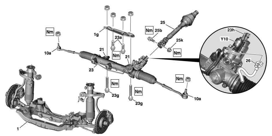
P46.20-2139-09
1 Front axle carrier
1g Retaining plate
10a Tie rod joints
21 Rubber bushing
23 Rack-and-pinion steering
25b Screw
25k Nut
26 Connector
Y10 SPS [PML] solenoid valve
23a Bolts
23g Bolts
23h Installation aid
25 Steering coupling


P46.20-2138-01
2 Cap
3 Bolts
23k Screw
30i Hydraulic line
30k Hydraulic line
30l Screw
P46.20-2137-01
Modification notes
| Removing | ||
Danger! | Risk of death caused by vehicle slipping or toppling off of the lifting platform. | Align vehicle between columns of vehicle lift and position four support plates at vehicle lift support points specified by vehicle manufacturer. | |
Danger! | Risk of injury to skin or eyes caused by hydraulic fluid spraying out under high pressure. Risk of poisoning caused by swallowing hydraulic fluid | Depressurize the hydraulic system completely before starting any work on the system. Wear protective clothing and safety glasses. | |
Danger! | Risk of injury caused by fingers being pinched or crushed when removing, installing or aligning hoods, doors, trunk lids, liftgates or sliding roof | Keep body parts and limbs well clear of moving parts. | |
| Notes on self-locking nuts and bolts | ||
1 | Open engine hood | ||
2.1 | Extract oil from expansion reservoir of power steering pump | Vehicles without active body control (ABC) | |
Hand pump | |||
2.2 | Suction off oil from the tandem pump expansion reservoirs | Vehicles with Active Body Control (Code 487) only. | |
Hand pump | |||
3 | Deactivate easy entry/exit function for driver seat and steering wheel | Otherwise the driver seat and steering wheel move to a different position, e.g. when the driver door is opened/closed. The upper frame may be damaged when the holding device is installed. | |
It is switched off using the buttons on the steering wheel in the "Comfort" menu on the multifunction display, see vehicle owner's manual. | |||
4 | Turn steering wheel to central position (front wheels in straight ahead position) and secure with the retaining device | On a disengaged steering coupling (25) the steering wheel should not be turned because the spiral contact coil will be destroyed. | |
Holding device | |||
5 | Remove the front wheels | ||
| Remove/install wheels, rotate if necessary | ||
6 | Remove center and rear sections of lower engine compartment paneling | ||
7 | Press tie rod joints (10a) off steering knuckles | ||
Thrust piece | |||
Puller | |||
8 | Unclip cap (2) | ||
9 | Remove bolts (3) from front diagonal struts | ||
10 | Disconnect plug (26) from SPS solenoid valve (Y10) | ||
11 | Unscrew nut (25k) | ||
12 | Loosen bolts (23a) for retaining plate (1g) on front axle carrier (1) | ||
13 | Remove bolts (23g) of retaining plate (1g) on front axle carrier (1) | ||
14 | Remove bolt (23k) for hydraulic line bracket (30i) | ||
15 | Remove bolt (30I) of the hydraulic line (30i) and hydraulic line (30k) on the rack-and-pinion steering (23) | Detach hydraulic lines (30i, 30k), seal line terminals with stop plugs. | |
Set of stop plugs | |||
16 | Pull out bolt (25b) | ||
17 | Move out rack-and-pinion steering (23) towards the front | ||
| Evaluating steering rack when repairing accident vehicles | ||
18 | Check rubber mount (21) on rack-and-pinion steering mounting for damage | Replace if required, see: | |
Remove rubber mount of rack-and-pinion mounting. | |||
Lubricant paste | |||
19 | Check protective cap on input shaft of rack-and-pinion steering (23) for damage | Replace if required, see: | |
Remove/install protective cap for input shaft on steering gear. | |||
| Install | ||
20 | Insert rack-and-pinion steering (23) into steering coupling (25) using installation aid (23h) | Do not remove installation aid (23h). | |
21 | Mount steering coupling (25) using bolt (25b) and nut (25k) to rack-and-pinion steering (23) | | |
22 | Fasten rack-and-pinion steering (23) to the front axle carrier (1) using bolts (23a) and bolts (23g) | Bolts (23a), bolts (23g), nuts and the area around the bolts must be free of oil and grease. Under exposure to heat the lubricants can liquify, allowing bolts and nuts to loosen. | |
| |||
| |||
23 | Screw in bolt (30I) for hydraulic line (30i) and hydraulic line (30k) to rack-and-pinion steering (23) | Install new sealing rings. | |
| |||
24 | Fix bracket for hydraulic line (30i) with bolt (23k) | ||
25 | Connect plug (26) to SPS solenoid valve (Y10) | ||
26 | Attach tie rod joints (10a) to steering knuckles | ||
| |||
27 | Screw in bolts (3) for front diagonal struts | Only tighten the bolts (3) for the diagonal struts once the vehicle is standing with its wheels on the ground. | |
| |||
28 | Clip on cap (2) | ||
29 | Fill power steering pump and bleed | Vehicles with Active Body Control (Code 487) only. | |
Vehicles without active body control (ABC) | |||
30 | Check steering for function and leaks | ||
31 | Mount front wheels | ||
| Remove/install wheels, rotate if necessary | ||
32 | Check front axle toe and adjust if necessary | When installing new parts. see: | |
Perform a wheel alignment check | |||
33 | Install lower engine compartment paneling | ||
34 | Close engine hood |
Steering shaft
Number | Designation | Model | ||
BA46.10-P-1002-01E | Locking screw and steering coupling locknut to rack-and-pinion steering | Nm | 24 | |
Tie rod
Number | Designation | Model | ||
BA46.40-P-1001-01E | Self-locking nut, tie rod to steering knuckle | Stage 1 | Nm | 50 |
Stage 2 | ° | 60 | ||
Steering gear
Number | Designation | Model | ||
BA46.20-P-1003-01E | Bolted connection, rack-and-pinion steering to retaining plate | Stage 1 | Nm | 70 |
Stage 2 | ° | 90 | ||
BA46.20-P-1004-01E | Bolted connection, supporting plate to front axle carrier | Stage 1 | Nm | 110 |
Stage 2 | ° | - | ||
BA46.20-P-1006-01E | Bolt on clamp plate, high-pressure line / return line to rack-and-pinion steering | Nm | 18 | |
Frame floor assembly
Number | Designation | Model | |
BA61.10-P-1011-01C | Self-locking bolt, front diagonal strut to frame floor assembly/front axle carrier | Nm | 70 |
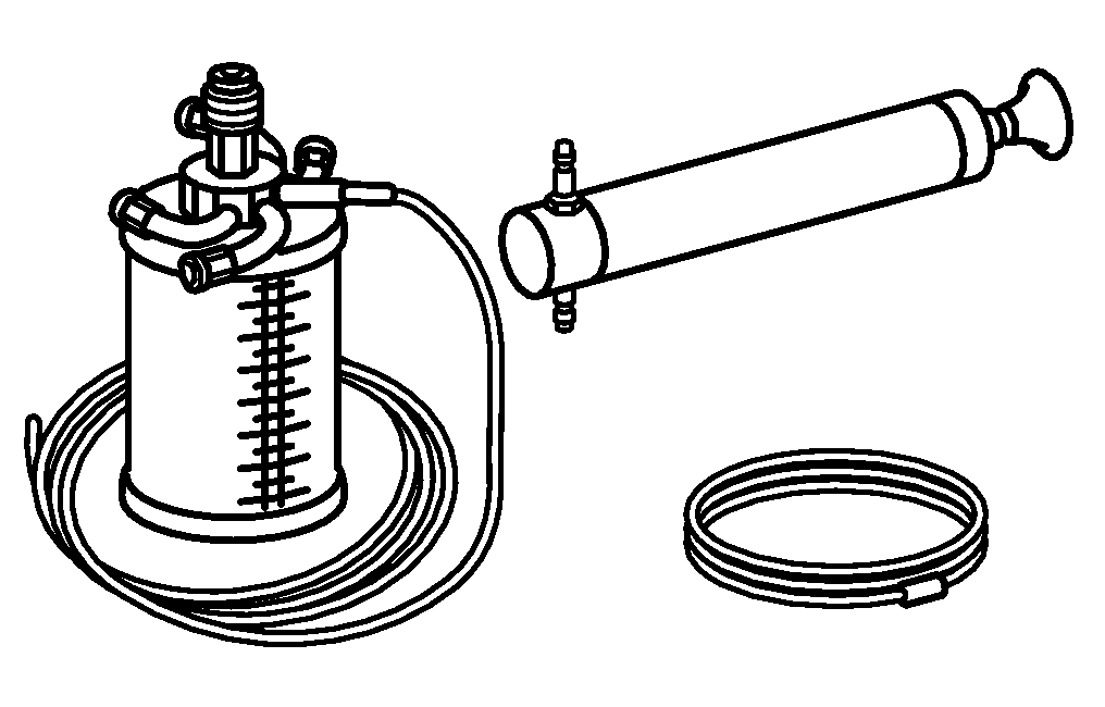


210 589 00 71 00
Thrust piece
Hand pump
Holding device
Puller
129 589 01 21 00
140 589 00 63 00
124 589 03 33 00

Set of stop plugs
129 589 00 91 00
Repair materials
Number | Designation | Order number |
BR00.45-Z-1002-06A | Lubricating paste, rubber parts 2.5 kg, DB supply specification 6867.00 | A 000 989 01 60 |