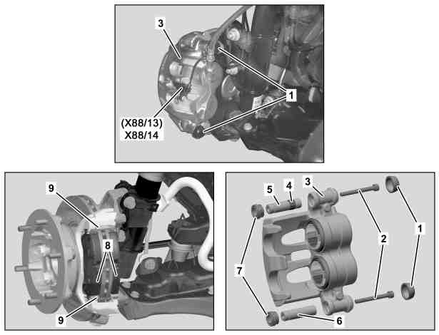
D42.10-1159-06
1 Dust caps
2 Bolts
3 Brake caliper
4 Rubber ring
5 Guide bolts
6 Guide bolts
7 Bellows
8 Brake linings
9 Anti-rattle spring
X88/13 Right front brake pad contact sensor connector
X88/14 Left front brake pad contact sensor connector
| Remove/install | ||
Danger! | Risk of poisoning caused by swallowing brake fluid. Risk of injury caused by brake fluid coming into contact with skin and eyes. | Only pour brake fluid into suitable and appropriately marked containers. Wear protective clothing and eye protection when handling brake fluid. | |
| Notes on repairs to brake system | ||
| Brake fluid notes | ||
1 | Remove wheels | ||
2 | Press back brake pads (8) using a suitable tool | If the brake fluid level in the reservoir is too high, suction off a little brake fluid. | |
3 | Disconnect right front brake pad contact sensor connector (X88/13) or left front brake pad contact sensor connector (X88/14) | Use straight or angled needle nose pliers. | |
4 | Remove dust caps (1) in top and bottom of brake caliper (3) | Installation: Replace dust caps (1). Clean dust cap seat and coat with lubricating grease from the repair kit. Pay attention to correct seat of dust caps (1). | |
Grease | |||
5 | Remove bolts (2) | | |
6 | Remove brake caliper (3) | Tie up brake caliper (3). Ensure that the brake hose is not subjected to tensile loads or angular movement. | |
7 | Remove brake pads (8) | Installation: When installing the old brake pads (8), install them again where they were removed from. | |
8 | Remove anti-rattle springs (9) from brake caliper support | Installation: Replace anti-rattle springs (9). Clean contact surfaces on brake caliper bracket. | |
9 | Clean brake parts and check for wear and damage | ||
Brake lining wear limit | |||
Front axle brake disks | |||
Caliper gauge | |||
Brake caliper brush | |||
If the wear limit has been reached, install new brake disks. See: | |||
Remove/install brake disks of front axle | |||
10 | Remove guide pins (5, 6) and boots (7) | First press guide pin (5, 6) out of guide in direction of brake disk, then remove boots (7). | |
Installation: Clean seat of guide pins (5, 6). Coat guide pins (5, 6), guide bore and boots (7) with lubricating grease from repair kit. First insert boots in the groove of the brake caliper (3), then push guide bolts (5, 6) into the guide from outside to inside towards the brake disk as when dismantling. Ensure that the boots (7) are correctly located in the groove of the guide pins (5, 6), otherwise the brake caliper (3) will no longer be able to move freely. Wipe off excess lubricating grease. | |||
Installation: Replace guide pins (5, 6). Install guide pin (5) with rubber ring (4) at the top, install guide pin (6) without rubber ring at the bottom. Allow existing air to escape from the boots (7). To do this, lift the boot (7) at one point slightly out of the groove of the guide pin (5, 6) and press out the air. | |||
Grease | |||
11 | Install in the reverse order | ||
12 | Build up brake pressure by fully depressing brake pedal several times | ||
13 | Check fluid level in reservoir, correct if necessary | Only when installing new brake linings (8). | |
14 | Check brake system for leaks |
Test values for front brake disks
Number | Designation | Model | Model | ||
BE42.10-N-1001-08B | Brake disk | Thickness when new | mm | 28 | 28 |
Wear limit | mm | 25 | 25 | ||
Lateral runout | mm | 0.03 | 0.03 | ||
Flatness deviation | mm | 0.04 | 0.04 | ||
Repair limit dimension | mm | - | - | ||
Test and adjustment values for service brake
Front axle brake caliper
Number | Designation | Model 900 | Model 906 | |||
BA42.10-N-1004-10H | Guide pin/catch bolt, top section of brake caliper to brake caliper support | M8 | Nm | 34 | 34 | |
M10/10.9 | Nm | - | - | |||


124 589 05 19 00
Vernier caliper
Brake caliper brush
000 589 26 68 00
Repair materials
Number | Designation | Order number |
BR00.45-Z-1092-06A | Lubricating grease (Brembo brake caliper guide) | A 002 989 51 51 |