
P40.10-2336-01
Only perform steps 1 to 4 if a new tire or support ring is being fitted.
1 Use a brush to apply a coating of MICHELIN tire bead lubricant to the entire circumference of the contact surface (cross-hatched section).
The MICHELIN tire bead lubricant is supplied with the support ring and tire.
2 Apply assembly paste to the tire bead.

P40.10-2337-10
3 Insert the support ring (1) into the tire from the side of the tire with the larger inside diameter.
The chambers of the support ring (1) must face the side of the tire with the smaller inside diameter. Press in the support ring (1) while simultaneously turning until it is between the tire beads on one side.
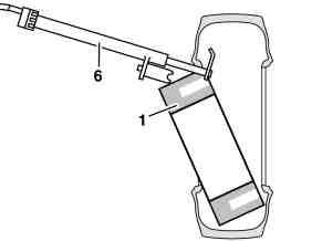
P40.10-2425-01
4 Position the hook of the clamp cylinder (6) in the tire as shown in the diagram and position the support of the clamp cylinder (6) against the support ring.
5 Draw in the hook of the clamp cylinder (6) to pull the support ring (1) into the tire.

P40.10-2339-01
6 Clamp the disk wheel on the assembly machine with the outside facing upward and coat the rim flange with assembly paste.
7 Push the tire with the installed support ring (1) onto the disk wheel as far as possible by hand.
The smaller inside diameter of the tire and the chambers in the support ring (1) must face upward.

P40.10-2340-10
8 Use the roller (2) of the upper mounting bar to press against the tire sidewall and turn the wheel until the support ring (1) rests against the disk wheel.
The alignment tabs (3) of the support ring (1) must be level with the shoulder of the drop center (arrow).

P40.10-2341-10
9 Insert the tire bead in one position on the drop center.
10 Position the roller (2) of the upper mounting bar on the tire bead and rim flange (arrow)
11 Secure the tire to prevent it from springing from its seat and mount the tire.
Mounting must be carried out as a single, uninterrupted process.
12 Place the roller (2) on the tire bead and rotate the wheel through approx. 2 additional turns.
This ensures that the tire is seated correctly on the rim and also minimizes imbalance.

P40.10-2342-01
13 Turn the wheel over on the assembly machine.
14 Use the assembly levers (4, 5) to pull the tire over the rim flange around the entire circumference.

P40.10-2343-10
15 Insert the tire bead in one position on the drop center.
16 Position the roller (2) of the upper mounting bar on the tire bead and rim flange (arrow)
17 Secure the tire to prevent it from springing from the drop center and mount the tire.
Mounting must be carried out as a single, uninterrupted process.
18 Place the roller (2) on the tire bead and rotate the tire through approximately 2 additional turns.
This ensures that the tire is seated correctly on the rim and also minimizes imbalance.