
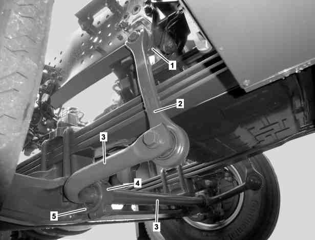
1st front axle, not driven |
1 | Vehicle frame bearing bracket |
2 | Torsion bar linkage |
3 | Torsion bar |
4 | Bearing cap |
5 | Front axle bearing bracket |
W32.35-1064-05
2nd front axle, not driven |
1 | Vehicle frame bearing bracket |
2 | Torsion bar linkage |
3 | Torsion bar |
4 | Bearing cap |
5 | Front axle bearing bracket |
W32.35-1069-06

1st front axle, driven |
1 | Vehicle frame bearing bracket |
2 | Torsion bar linkage |
3 | Torsion bar |
4 | Bearing cap |
5 | Front axle bearing bracket |
W32.35-1066-05

2nd front axle, driven |
1 | Vehicle frame bearing bracket |
2 | Torsion bar linkage |
3 | Torsion bar |
4 | Bearing cap |
5 | Front axle bearing bracket |
W32.35-1067-06
Topical note | Notes on threaded connections fastened using a tightening angle-based tightening process | ||
Notes on safety-relevant components | |||
| Remove | ||
1 | Remove torsion bar (3) at torsion bar linkages (2). | ||
2 | Detach bearing caps (4) from both front axle bearing brackets (5). | ||
3 | Remove torsion bar (3) from front axle bearing brackets (5). | ||
4 | Remove torsion bar linkage (2) at vehicle frame bearing brackets (1). | ||
| Check | ||
5 | Check bearing bushings on torsion bar (3) in area of front axle bearing brackets (5) for damage and wear. | If damage or wear is visible: | |
| |||
Attach new bearing bushings to torsion bar (3) in area of front axle bearing brackets (5). | |||
6 | Check bearing bushings at torsion bar linkages (2) for damage and wear. | If damage or wear is visible: | |
| |||
attach new bearing bushings at torsion bar linkages (2). | |||
Hand pump | |||
Hollow cylinder | |||
Hydraulic hose (complete) | |||
Threaded spindle | |||
Removal and installation tool | |||
Removal and installation tool | |||
Sleeve | |||
Removal and installation tool | |||
Sleeve | |||
Extraction and insertion tool | |||
Press-in/out tool | |||
7 | Check bearing bushings on torsion bar (3) for damage and wear. | If damage or wear is visible: | |
| |||
attach new bearing bushings to torsion bar (3). | |||
Hand pump | |||
Hollow cylinder | |||
Hydraulic hose (complete) | |||
Threaded spindle | |||
Removal and installation tool | |||
Removal and installation tool | |||
Sleeve | |||
Removal and installation tool | |||
Sleeve | |||
Extraction and insertion tool | |||
Press-in/out tool | |||
| Install | ||
8 | Attach torsion bar linkage (2) to vehicle frame bearing brackets (1). | Do not tighten the bolts yet. | |
9 | Attach torsion bar (3) to torsion bar linkages (2). | Do not tighten the bolts yet. | |
10 | Attach torsion bar (3) with bearing caps (4) to front axle bearing brackets (5). | Do not tighten the bolts yet. | |
11 | Tighten screws of torsion bar linkages (2) at vehicle frame bearing brackets (1). | Torsion bar linkage at vehicle frame bearing bracket | |
12 | Tighten screws securing torsion bar (3) to torsion bar linkages (2). | Torsion bar at torsion bar linkage | |
13 | Tighten screws of bearing caps (4) on front axle bearing bracket (5). | Bearing cap of torsion bar to front axle bearing bracket |


652 589 00 33 16
Sleeve
950 589 01 33 00
Press-in/out tool
652 589 00 33 21
Hand pump
652 589 00 33 22
Hollow cylinder


652 589 00 33 01
Removal and installation tool
652 589 00 33 02
Removal and installation tool
652 589 00 33 11
Threaded spindle
652 589 00 33 15
Sleeve


652 589 00 33 23
Hydraulic hose (complete)
963 589 00 33 00
Extraction and insertion tool
950 589 02 33 00
Removal and installation tool