
P27.50-0291-09

P27.50-0292-06
14a External plate carrier B2 / piston B3
14b-d Seal rings on piston/multidisk brake B3
27 Piston/multidisk brake B2
28 Piston guide ring
28a-b Seal rings on piston guide ring
29 Disk spring/piston pushback
30 Spring cup
31 Snap ring
32 Piston guide/multidisk brake B2 and B3
32a O-ring
134 Disk pack B2
134a Snap ring
134b Disk spring/disk pack

P27.50-0299-11
074 Assembly tool
31 Snap ring
P27.50-0288-11
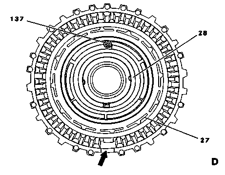
27 Piston B2
28 Piston guide ring
137 Valve

P27.50-0287-11
Oil pressure supply:
A Bore for piston B3
B Bore for piston B2/reciprocal side (piston guide ring)
C Bore for oil pressure to multidisk clutch K3
D Bore for piston B2/switching side
Modification notes
| Removing | ||
1 | Remove disk pack B2 (134) | ||
| Disassemble | ||
2 | Remove snap ring (134a) | ||
3 | Remove disk pack B2 (134) and disk spring (134b) from external plate carrier B2 | The external plate carrier B2 for the multidisk brake B2 also serves as the piston B3 for the multidisk brake B3. | |
Check multi-disks for scorch marks and wear. | |||
4 | Place assembly device (074) on disk spring (29) and tension until groove for snap ring (31) is exposed (picture C) | | |
5 | Remove snap ring (31) | ||
6 | Remove spring plate (30) and disk spring (29) | ||
7 | Separate piston guide ring (28) and piston/multidisk brake B2 (27) from piston B3 (14a); to do so, blow compressed air into hole (D) (picture E) | ||
8 | Press piston guide ring (28) out of piston B2 (27) | ||
| Peak-to-valley height on piston B2 changed | ||
| Piston B2 modified | ||
9 | Separate piston guide (32) from piston B3 (14a); to do so, blow compressed air into hole (A) (picture E) | ||
| Assemble | ||
10 | Assemble piston guide (32) and piston B3 (14a) at correct position | ||
11 | Insert piston/multidisk brake B2 (27) into piston B3 (14a) | Check all seal rings; replace if necessary With seal rings (14c), (28a) and (28b), the rounded edges must face outward. With seal ring (14d), the rounded edges must face inward. (Picture B) | |
12 | Insert piston guide ring (28) | The valve (137) in the piston guide ring must be at the top (picture D). | |
13 | Insert disk spring (29) and spring plate (30) | Insert the disk spring with the curvature toward the spring plate. | |
14 | Place assembly device (074) on disk spring (29) and tension until groove for snap ring (31) is exposed | | |
15 | Insert snap ring (31) | ||
16 | Insert disk spring (134b) and disk pack B2 (134) into external plate carrier B2 and measure | Observe externally-toothed plate sequence. | |
Play in multiple-disc brake B2 | |||
| |||
| Survey of multi-disk components, production details | ||
| End disk modified | ||
17 | Attach snap ring (134a) | ||
| Install | ||
18 | Install disk pack B2 (134). |
Adjustment values of multi-disk clutch
Number | Designation | Trans-mission 722.6 | |||
BE27.50-P-1002-02B | Play in multiple-disc brake B2 | Number of multiple-discs | 4 | mm | 1.90...2.30 |
5 | mm | 2.00...2.40 | |||
6 | mm | - | |||


208 589 00 21 00
Thrust device
Assembly tool
140 589 13 43 00