AR26.35-W-1000B | Remove/install shift rod and shift piston for splitter group | 27.2.12 |
TRANSMISSION 715.320

W26.35-1009-06
1 Shift cylinder
2 Shift piston
3 Rubber sealing ring
4 Shift rod
5 Bearing bolt
6 Screw plug
7 Spring
8 Spring
9 Catch bolt
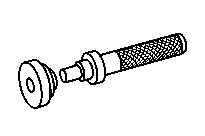
10 Assembly tool
11 Pilot bushing
12 Radial shaft seal
13 Shim
Modification notes
| Removing | ||
1 | Remove shift cylinder (1) of splitter group | ||
2 | Unscrew screw plug (6), remove springs (7, 8) and catch bolt (9) | The screw plug (6) is spring-loaded. | |
3 | Unscrew both bearing pins (5) | ||
4 | Pull out shift rod (4) with shift piston (2) | To remove, tilt shift fork and twist shift rod (4). | |
5 | Detach rubber sealing ring (3) | ||
Danger! | Risk of injury to skin and eyes caused by handling hot or glowing objects. | Wear safety gloves, protective clothing and safety glasses, if necessary. | |
6 | Heat up shift piston (2) to apron. 80 °C and unscrew from the shift rod (4) and remove shim (13) | Pronged wrench | |
Holding device | |||
7 | Remove pilot bushing (11) and radial shaft sealing ring (12) for shift rod (4) of splitter group | ||
Internal extractor | |||
Countersupport | |||
| Adapter for removing guide bush in front section of transmission housing | ||
| Install | ||
8 | Install radial shaft sealing ring (12) and pilot bushing (11) for shift rod (4) of splitter group | ||
Drift | |||
Lubricant | |||
9 | Install shift rod (4) using assembly tool (10) and attach shift fork in shift rod (4) | Attach shift fork in shift rod (4) using a small screwdriver through the hole of the left bearing pin (5). | |
| Assembly tool for installing splitter group shift rod | ||
10 | Install both bearing pins (5) | Insert bearing pins (5) using thread locking compound. | |
| |||
11 | Install catch bolt (9), springs (7, 8) and screw plug (6) | | |
12 | Determine size of shim (13) for shift piston (2) of splitter group | ||
13 | Pull shift rod (4) all the way out using the assembly tool (10) | ||
| Assembly tool for installing splitter group shift rod | ||
14 | Fit determined shim (13) on shift rod (4) | ||
15 | Pull rubber sealing ring (3) onto shift piston (2) and install shift piston (2) on shift rod (4) | Coat rubber sealing ring (3) using lubricant. | |
Secure shift piston (2) using locking agent. | |||
| |||
Pronged wrench | |||
16 | Determine size of shim for shift cylinder (1) of splitter group | ||
Internal extractor | |||
Countersupport | |||
Inspection and adjustment data: splitter unit (splitter group)
Number | Designation | Transmission | |
BE26.35-N-1001-01A | Adjustment dimension for gearshift piston of cascade box | mm | 0.3...0.5 |
BE26.35-N-1002-01A | Adjustment dimension for splitter box shift cylinder | mm | 0.4...0.5 |
Splitter group
Number | Designation | Transmission | ||
BA26.35-N-1001-01A | Shift fork bearing bolt to transmission housing | Nm | 120 | |
BA26.35-N-1002-01A | Shift piston to splitter group shift rod | With special tool | Nm | 90 |
Without special tool | Nm | 95 | ||
Housing
Number | Designation | Trans-mission | |
BA26.40-N-1008-01D | Splitter group shift lock to transmission housing | Nm | 30 |


000 589 33 33 00
000 589 34 33 00
000 589 27 33 00
000 589 30 33 00
Counter stay
Internal puller
Internal puller
Counter stay


715 589 02 07 00
Holding device
Puller
Drift
714 589 05 15 00
715 589 00 31 00
Repair materials
Number | Designation | Order number |
BR00.45-Z-1008-02A | Quick-acting adhesive, Loctite 270 | A 002 989 93 71 |
BR00.45-Z-1027-06A | Synthetic grease 50 g | A 001 989 32 51 10 |
BR00.45-Z-1133-02A | Loctite 243 | A 613 989 09 71 |