
P09.10-2451-09
Shown on model 177 |
1 | Line bracket | 5s | Screw | 9 | Air intake pipe | ||
2 | Clean air line | 6 | Bracket | 10 | Clamp | ||
3 | Threaded clamps | 6s | Bolts | 11 | Bolts | ||
4 | Electrical connector | 8 | Vent line | 12 | Seal | ||
5 | Bracket |
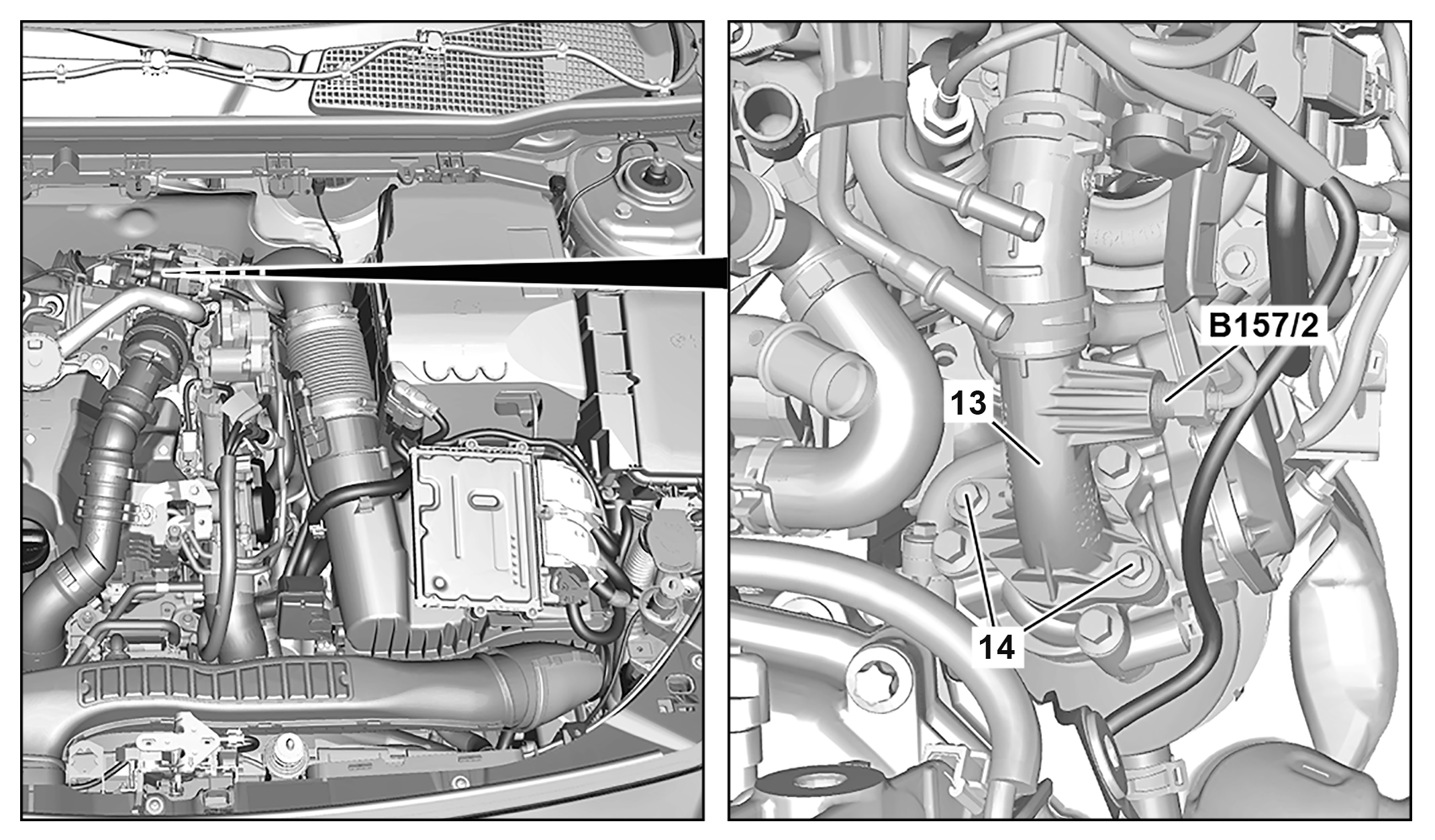
Shown on model 177 |
13 | Exhaust gas recirculation line |
14 | Bolts |
B157/2 | Low-pressure exhaust gas recirculation temperature sensor |
P14.20-A034-05
Warning | Risk of burn injuries, suffocation and poisoning when working on the exhaust system and the components connected to it. Risk of suffocation and risk of poisoning caused by inhalation of gaseous and solid components of the exhaust. Risk of poisoning caused by skin contact with solid components of the exhaust. | Wear protective clothing and safety glasses. Use the extraction system. Move people out of the hazard area. | |
Caution | Risk of injury caused by scraping or cutting body parts on sharp vehicle parts | Always wear protective gloves when working on or near sharp and non-deburred vehicle parts. | |
Caution | Risk of injury to skin and eyes due to handling of engine oil. Risk of poisoning caused by swallowing engine oil | Wear protective gloves, protective clothing and safety glasses. | |
Topical note | Information on preventing damage to electronic components due to electrostatic discharge | ||
Topical note | Notes on avoiding damage through contamination and foreign objects | ||
Notes on safety-relevant components | |||
| Remove/install | ||
1 | Switch off ignition and store transmitter key outside of transmitter range (min. 2 m). | ||
2 | Remove upper engine cover. | ||
| |||
Installation: Only install upper engine cover after the leak test. | |||
3 | Unclip line bracket (1) from clean air line (2). | ||
4 | Release threaded clamps (3) from clean air line (2) and remove clean air line (2). | ||
5 | Release and disconnect electrical connector(4). | ||
6 | Remove screw (5s). | Bolt, holder for sensor wiring harness to air intake pipe | |
7 | Unclip electric line at bracket (5) and remove bracket (5). | | |
8 | Unscrew screws (6s) and place bracket (6) to one side. | | |
Bolt, holder for differential pressure sensor to exhaust gas turbocharger | |||
9 | Remove bleed line (8) from air intake pipe (9). | Hose clamp pliers | |
10 | Remove screws (11). | Bolt, air intake pipe to turbocharger | |
11 | Remove low-pressure exhaust gas recirculation temperature sensor (B157/2). | Temperature sensor to EGR line | |
12 | Remove screws (14). | Bolt, EGR line to exhaust gas recirculation valve | |
13 | Remove exhaust gas recirculation line (13) with air intake pipe (9) and seal opening with suitable stop plug. | Installation: Install new seal (12). | |
Record plug | |||
14 | Release clamp (10) and remove hose with exhaust gas recirculation line (13). | If air intake pipe (9) will be replaced. | |
Hose clamp pliers | |||
15 | Install in the reverse order. | ||
16 | Read out fault memory, clear if necessary. | ||
| |||
| Check | ||
Warning | Risk of accident from vehicle starting off by itself when engine running. Risk of injury (bruises and burns) resulting from working on the engine while it is being started or when it is running. | Secure vehicle to prevent it from starting off by itself. Wear closed and snug-fitting work clothes. Do not touch hot or rotating parts. | |
17 | Perform engine test run. While doing so, check engine for proper operation and leak tightness. | ||
18 | Install upper engine cover. | ||
|


454 589 00 37 00
Hose clamp pliers
129 589 00 91 00
Record plug