
W05.20-1037-08
Shown on engine 471.9 up to engine end number 124618 |
1 | Cylinder head cover | 5 | Fuel high-pressure lines | B601 | Camshaft position sensor | ||
2 | Intermediate frame | 6 | High-pressure lines | B622 | Rail pressure sensor | ||
3 | Engine wiring harness | 7 | Fuel return line | ||||
4 | Camshaft housing | 8 | Sealing rings |

Shown on engine 470.9 |
4 | Camshaft housing |
10 | Bracket (only on engine 470.9) |
11 | Coolant line (only for engine 470.9) |
12 | Ventilation pipe (only for engine 470.9) |
W05.20-1053-06

W05.20-1047-08
Shown on engine 470.9 |
4 | Camshaft housing | 12 | Ventilation pipe (only for engine 470.9) | Y625 | Engine brake solenoid valve, stage 2 | ||
5 | Fuel high-pressure lines | 13 | Bracket (only on engine 470.9) | ||||
9 | Adapter set | Y624 | Engine brake solenoid valve, stage 1 |
Warning | Risk of accident from vehicle starting off by itself when engine running. Risk of injury (bruises and burns) resulting from working on the engine while it is being started or when it is running. | Secure vehicle to prevent it from starting off by itself. Wear closed and snug-fitting work clothes. Do not touch hot or rotating parts. | |
Warning | Risk of injury caused by body parts being pinched or crushed as cab is tilted | Ensure that no one is within the tilting range of the cab as it is being tilted. Always tilt the cab all the way to the end position and secure with the safety strut. | |
Topical note | Notes on tilting the cab | ||
Topical note | Notes on self-locking nuts and bolts | ||
Topical note | Notes on avoiding damage through contamination and foreign objects | ||
Note on calculation of tightening torque when using insertion or socket tools with various effective lengths | |||
Notes on safety-relevant components | |||
| Remove/install | ||
1 | Tilt cab. | Installation: Only tilt back cab after the leak test. | |
2 | Remove noise encapsulation. | ||
3 | Remove premuffler with bracket. | Only on vehicles with code M5Y (Engine version Euro VI). | |
4 | Remove the cylinder head cover (1). |
| |
ENGINE 470.9 | |||
5.1 | Remove intermediate frame (2). | Engine 470.9 up to engine end number 222433, 471.9 up to engine end number 124618 | |
5.2 | Remove wiring harness of the fuel injectors. | Engine 470.9 as of engine end number 222434, engine 471.9 as of engine end number 124619, | |
6 | Attach adapter set (9) to the camshaft housing (4). | Adapter set | |
7 | Mount turning device onto timing case. | ||
Bracket for front axle travel sensor to crescent-shaped crossmember | |||
Screw/bolt, cap of TDC inspection hole to timing case | |||
Bolt, turning device to timing case | |||
Turning device | |||
8 | Set engine to ignition TDC on cylinder 1 and engage. | ||
| Gearwheel drive modified | ||
Up to engine end number 206646 | |||
From engine end number 206647 | |||
Do not change the ignition TDC setting or engagement during the removal/installation of the camshafts. | |||
Installation: Pull out drift on timing case and remove template. Install crankshaft position sensor with the new sealing ring and attach the electrical connection to crankshaft position sensor if necessary. | |||
Bolt, crankshaft position sensor to timing case | |||
Template | |||
Template | |||
Turning device | |||
Drift | |||
9 | Remove rocker arm assembly. |
| |
Exhaust rocker arm assembly | |||
10 | Disconnect electrical connection on camshaft position sensor (B601). | ||
11 | Disconnect electrical connection from rail pressure sensor (B622). | ||
12 | Expose engine wiring harness (3) in the area of the camshaft housing (4). | ||
13 | Remove the bracket (10) of the coolant line (11) from the camshaft housing (4). | Only for engine 470.9 | |
14 | Remove bracket (13) of the compressor air intake hose. | Only for engine 470.9 | |
15 | Remove high-pressure lines (6) to rail. |
| |
Engine 471.9 up to engine end number 032690 | |||
16 | Remove fuel return line (7) from the rail. | Installation: Install new sealing rings. | |
Engine 470.9, 471.9Banjo bolt, fuel line to rail (pressure limiting valve return) | |||
17 | Seal connections of the rail with protective covers. | | |
Set of protective covers | |||
18 | Remove fuel high-pressure lines (5) to the fuel injectors. | ||
19 | Seal connections of the fuel injectors with protective covers. | | |
Set of protective covers | |||
20 | Remove screws of the camshaft housing (4). | Tightening procedure | |
Unfasten screw/bolts in reverse order of the tightening procedure. | |||
Bolt, camshaft case with rocker arm bracket to cylinder head | |||
21 | Remove camshaft housing (4) with camshafts. | Installation: Check marking on the camshaft sprockets relative to the markings on the template; align camshaft sprockets if necessary. | |
For engine 470.9 | |||
Template | |||
Template | |||
22 | Remove seal from camshaft housing (4). | Installation: Clean sealing surfaces on cylinder head and camshaft housing (4). Replace seal. | |
23 | Remove sealing ring of the vent tube (12). | Only for engine 470.9. | |
Installation: Replace sealing ring. | |||
24 | Remove template and adapter set (9) from the camshaft housing (4). | Only when installing new camshaft housing (4). | |
25 | Remove seals (8). | Only when installing new camshaft housing (4). | |
Installation: Install new seals (8). | |||
26 | Pull engine brake solenoid valve, stage 1 (Y624) and engine brake solenoid valve, stage 2 (Y625) out of the camshaft housing (4). | Only when installing new camshaft housing (4). | |
Installation: Install new sealing rings. | |||
27 | Remove camshaft position sensor (B601) from camshaft housing (4). | Only when installing new camshaft housing (4). | |
Installation: Replace sealing ring. | |||
Bolt, camshaft position sensor to camshaft housing | |||
28 | Remove camshafts. | Only when installing new camshaft housing (4). | |
29 | Remove rail. | Only when installing new camshaft housing (4). | |
30 | Install in the reverse order | ||
31 | Perform engine test run. | ||
32 | Check engine in the area of the cylinder head cover (1), intermediate frame (2), and camshaft housing (4) for leak tightness. | Visual inspection. |


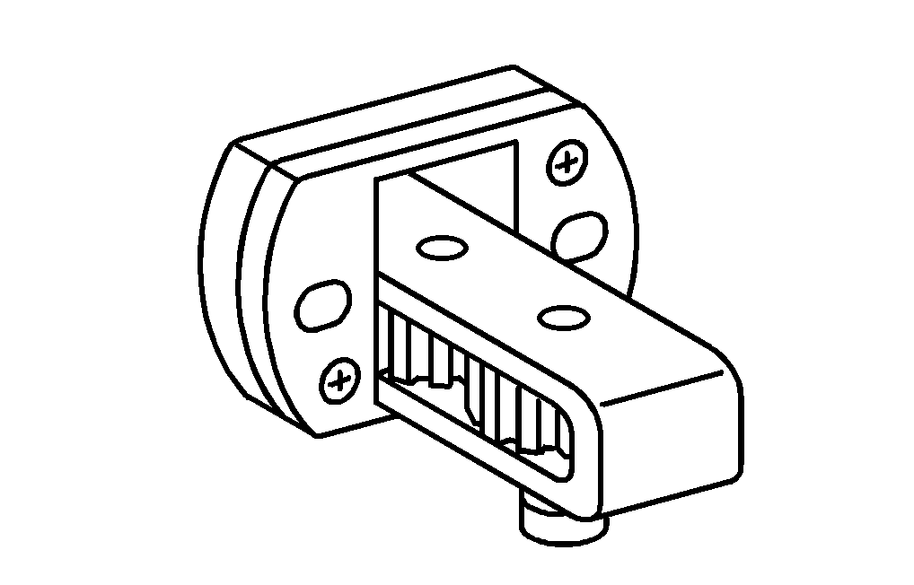

470 589 06 23 00
Template
470 589 00 15 00
Drift
904 589 04 63 00
Turning device
470 589 02 63 00
Adapter set


470 589 27 91 00
Set of protective covers
470 589 03 23 00
Template
เอกสารที่อ้างถึง
- ah0000n000101a
- ah0000n500001h
- ah0000p001501cw
- ah0000z001901a
- ah6080n000301a
- ar0120w5014ha
- ar0120w5014hb
- ar0120w5016h
- ar0330w160003h
- ar0330w160003h
- ar0500w5521ha
- ar0500w5521ha
- ar0500w5521hb
- ar0510w762003h
- ar0510w762003ha
- ar0520w6992h
- ar0520w699501h
- ar0703w1010h
- ar0716w1003h
- ar0716w1004h
- ar0716w1004ha
- ar0716w1008h
- ar4910w4930h
- as0000z000501a
- as6080z000101a
- bt0510w000201a