
S05.20-4504-09
1 Belt pulley
2 Inlet camshaft
5 Scribe marks
3 Retaining pin
4 Camshaft bearing
| Remove | ||
Danger! | Risk of injury from grazing or cutting body parts on sharp vehicle parts | Always wear protective gloves when working on or near sharp and untrimmed vehicle parts. Deburr metal repairs. | |
1 | Remove cylinder head cover | ||
2 | Position piston of cylinder 1 to ignition TDC | Crank engine at crankshaft and position belt pulley (1) on marking. | |
Socket wrench bit | |||
3 | Lock inlet camshaft (2) | Push the retaining pin (3) at the camshaft bearing (4) into the hole in the intake camshaft sprocket. | |
Locking pins | |||
| Inspect | ||
4 | Inspect basic position of camshafts | The two markings (B) in the intake camshaft sprockets must be positioned opposite and the markings of the camshaft and camshaft bearing cap must be aligned (arrows). Piston of cylinder 1 at ignition TDC. if necessary: | |
Set the basic position of camshafts | |||
| Install | ||
5 | Install cylinder head cover |

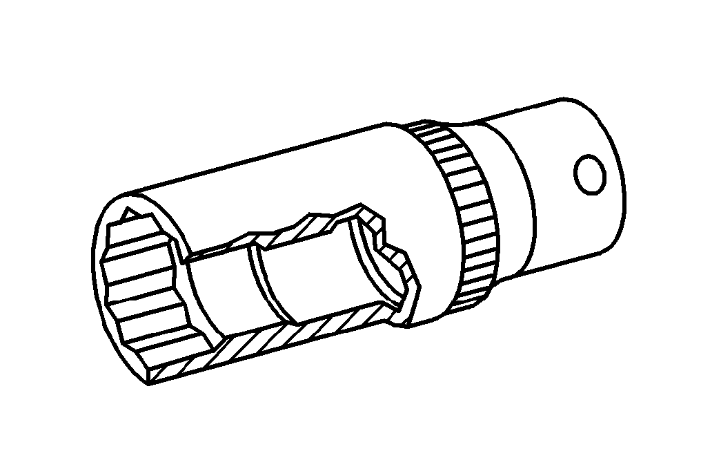
111 589 03 15 00
Retaining pins
Wrench socket
001 589 65 09 00
Documentos referenciados
- ar0120s5014sd
- ar0520s6020sd
- as0000z001701a Risco de lesão por corte ou arranhão em peças com cantos cortantes ou rebarbas nos veículos